Ryobi P881 User Manual 5 - Page 8
Operation
 |
View all Ryobi P881 manuals
Add to My Manuals
Save this manual to your list of manuals |
Page 8 highlights
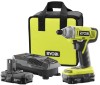
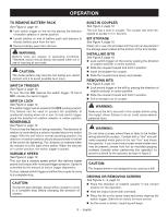
OPERATION TO REMOVE BATTERY PACK See Figure 2, page 10. Lock switch trigger on the tool by placing the direction of rotation selector in center position. Locate latches on end of battery pack and depress to release battery pack from the tool. Remove battery pack from the tool. WARNING: Battery tools are always in operating condition. Therefore, switch should always be locked when not in use or carrying at your side. CAUTION: The metal surface may become hot during use. Avoid contact with it to avoid possible burn injury. SWITCH TRIGGER See Figure 3, page 10. To turn the tool ON, depress the switch trigger. To turn it OFF, release the switch trigger. SWITCH LOCK See Figure 3, page 10. The switch trigger can be locked in the OFF (center) position. This feature can be used to prevent the possibility of accidental starting when not in use. To lock switch trigger, place the direction of rotation selector in center position. REVERSIBLE See Figure 3, page 10. This tool has the feature of being reversible. The direction of rotation is controlled by a selector located above the switch trigger. With the tool held in normal operating position, the direction of rotation selector should be positioned to the left of the switch for tightening. The direction is reversed when the selector is to the right of the switch. When the selector is in center position, the switch trigger is locked. VARIABLE SPEED See Figure 3, page 10. This tool has a variable speed switch that delivers higher speed and torque with increased trigger pressure. Speed is controlled by the amount of switch trigger depression. To stop, release switch trigger and allow the coupler to come to a complete stop. CAUTION: To prevent gear damage, always allow coupler to come to a complete stop before changing the direction of rotation. BUILT-IN COUPLER See Figure 3, page 10. The tool has a built-in coupler. The coupler has been designed to accept 1/4 in. hex bits. BIT STORAGE See Figure 4, page 10. When not in use, bits provided with the tool can be placed in the storage area located at the bottom of the tool handle. INSTALLING BITS See Figure 5, page 10. Lock switch trigger on the tool by placing the direction of rotation selector in center position. Slide the coupler forward and hold in position. Insert bit straight into coupler. Slide the coupler back slowly and release. REMOVING BITS See Figure 5, page 10. Lock switch trigger or the drill by placing the direction of rotation selector in center position. Slide the coupler forward and hold in position. Pull bit straight out of coupler. WARNING: Make sure the bit is secured in the coupler before using the impact driver. Failure to do so could cause serious personal injury. WARNING: Do not drive a screw where there is likely to be hidden wiring behind the surface. Contact with a "live" wire will make exposed metal parts of the tool "live" and shock the operator. If you must drive a screw where hidden wire may be present, always hold tool by insulated gripping surfaces (handle) when performing the operation to prevent a shock to the operator, as seen in figure 6. CAUTION: The impact driver is not designed to be used as a drill. driving or removing screws See Figures 5 - 6, page 10. Place the direction of rotation selector in the correct position for the operation. Hold the impact driver with one hand. Place the bit on the screw head and slowly depress the switch trigger. Start the bit slowly for more control. As the screw is driven, impacting will begin. 8 - English
-
 1
1 -
2
-
 3
3 -
 4
4 -
 5
5 -
 6
6 -
 7
7 -
 8
8 -
 9
9 -
 10
10 -
 11
11 -
 12
12 -
 13
13 -
14
-
15
-
16
-
17
-
18
-
19
-
20
-
21
-
22
-
23
-
24
-
25
-
26
-
27
-
28
 |
 |