Ryobi RTS10 English Manual - Page 11
Know Your Table Saw, Overview, Warning - 10 table saw parts
 |
View all Ryobi RTS10 manuals
Add to My Manuals
Save this manual to your list of manuals |
Page 11 highlights
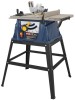
FEATURES KNOW YOUR TABLE SAW See Figure 2. The safe use of this product requires an understanding of the information on the tool and in this operator's manual as well as a knowledge of the project you are attempting. Before use of this product, familiarize yourself with all operating features and safety rules. OVERVIEW The upper portion of the blade projects up through the table, surrounded by an insert called the throat plate. The height of the blade is set with a blade adjusting handle on the front of the cabinet. To cut wood at a bevel, the blade must be tilted using the blade adjusting handle, the bevel lock lever, and the bevel indicator found on the front of the cabinet. Detailed instructions are provided in the Operation section of this manual for the basic cuts: rip cuts, cross cuts, miter cuts, bevel cuts, and compound cuts. This saw includes a rip fence and miter gauge. The rip fence is used to position work that will be cut lengthwise (rip cuts). Push smaller pieces with a push block or push stick. A scale on the front of the saw table shows the distance between the rip fence and the blade. For cuts with the blade straight up and cutting across the grain (cross cuts or miter cuts), use the miter gauge to set the angle and push the wood into the blade. Use the miter gauge for a bevel cross cut (compound cut) and the rip fence for a bevel rip cut. The blade guard assembly includes a spreader which is a metal device directly behind and above the blade. It is used to help keep the cut wood from binding together and causing possible kickback. It is very important to use the spreader for all through-sawing operations. The anti-kickback pawls (also a part of the blade guard assembly) are toothed plates mounted on the spreader. Their teeth point away from the work in case the work should be thrown or pulled back toward the operator. Then the teeth dig into the wood to help prevent or reduce the possibility of kickback. ANTI-KICKBACK PAWLS - Kickback is a hazard in which the workpiece is thrown back toward the operator. The toothed pawls are designed to snag the workpiece to prevent or reduce injury should kickback occur. BEVEL SCALE - The easy-to-read scale on the front of the cabinet shows the exact blade angle. BLADE - This saw comes with a 10 in, 24-tooth blade. The blade is adjusted with the blade adjusting handle on the front of the cabinet. Bevel angles are locked with a bevel locking lever below the front rail. WARNING: Do not use blades rated less than the speed of this tool. Failure to heed this warning could result in personal injury. BLADE ADJUSTING HANDLE - Use this handle to set the angle of the blade for bevel cuts and to lower or raise the blade for adjustments. This handle is located on the front of the cabinet. BLADE GUARD - Always keep the guard down over the blade for through-sawing cuts. Bevel LOCKING LEVER - This lever, placed just under the worktable surface on the front of the cabinet, locks the angle setting of the blade. Be sure the lever is unlocked before tilting the blade. If it is not unlocked, it may jam and bend the locking bolt. MITER GAUGE - This miter gauge aligns the wood for a cross cut. The easy-to-read indicator shows the exact angle for a miter cut. MITER GAUGE GROOVEs - The miter gauge rides in these grooves on either side of the blade. RIP FENCE - A metal fence guides the workpiece and is secured with a locking lever. When the locking lever is in the locked position, it cannot be unlocked until the trigger lock is pulled. SCALE - Found on the front of the saw table, the easy-toread scale provides precise measurements in rip cuts. SPREADER - A metal piece, slightly thinner than the saw blade, which helps keep the kerf open and prevent kickback. SWITCH ASSEMBLY - The saw has an easy access power switch located below the front rail. The switch key must be inserted into the switch before the saw can be operated. To lock the switch in the OFF position, remove the switch key from the switch. Place the key in a location that is inaccessible to children and others not qualified to use the tool. 11
-
 1
1 -
2
-
3
-
4
-
5
-
 6
6 -
 7
7 -
 8
8 -
 9
9 -
 10
10 -
 11
11 -
 12
12 -
 13
13 -
 14
14 -
 15
15 -
 16
16 -
17
-
18
-
19
-
20
-
21
-
22
-
23
-
24
-
25
-
26
-
27
-
28
-
29
-
30
-
31
-
32
-
33
-
34
 |
 |
