Ryobi RY10520 Operator's Manual - Page 31
Top Plate Filing Angle, Side Plate Angle, Maintaining Depth Gauge, Clearance
 |
View all Ryobi RY10520 manuals
Add to My Manuals
Save this manual to your list of manuals |
Page 31 highlights
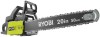
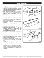
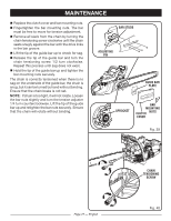
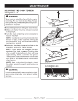
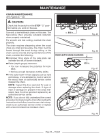
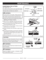
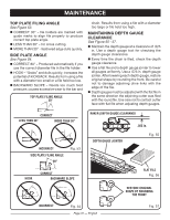
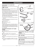
MAINTENANCE TOP PLATE FILING ANGLE See Figure 53. n CORRECT 30° - file holders are marked with guide marks to align file properly to produce correct top plate angle. n LESS THAN 30° - for cross cutting. n MORE THAN 30° - feathered edge dulls quickly. SIDE PLATE ANGLE See Figure 54. n CORRECT 80° - Produced automatically if you use the correct diameter file in the file holder. n HOOK - "Grabs" and dulls quickly; increases the potential of KICKBACK. Results from using a file with a diameter too small or a file held too low. n BACKWARD SLOPE - Needs too much feed pressure; causes excessive wear to the bar and TOP PLATE FILING ANGLE 30° chain. Results from using a file with a diameter too large or file held too high. MAINTAINING DEPTH GAUGE CLEARANCE See Figure 55 - 57. n Maintain the depth gauge at a clearance of .025 in. Use a depth gauge tool for checking the depth gauge clearances. n Every time the chain is filed, check the depth gauge clearance. ■n Use a flat file and a depth gauge jointer to lower all gauges uniformly. Use a .025 in. depth gauge jointer. After lowering each depth gauge, restore original shape by rounding the front. Be careful not to damage adjoining drive links with the edge of the file. ■n Depth gauges must be adjusted with the flat file in the same direction the adjoining cutter was filed with the round file. Use care not to contact cutter face with flat file when adjusting depth gauges. CORRECT LESS THAN 30° MORE THAN 30° INCORRECT SIDE PLATE FILING ANGLE 80° Fig. 53 HOOK CORRECT BACKWARD SLOPE RAKER (DEPTH GAUGE) CLEARANCE DEPTH GAUGE JOINTER .025 in. Fig. 55 FLAT FILE Fig. 56 RESTORE ORIGINAL SHAPE BY ROUNDING THE FRONT INCORRECT Fig. 54 Page 31 - English Fig. 57
-
 1
1 -
2
-
3
-
4
-
5
-
6
-
7
-
8
-
9
-
10
-
11
-
12
-
13
-
14
-
15
-
16
-
17
-
18
-
19
-
20
-
21
-
22
-
23
-
24
-
25
-
 26
26 -
 27
27 -
 28
28 -
 29
29 -
 30
30 -
 31
31 -
 32
32 -
 33
33 -
 34
34 -
 35
35 -
 36
36 -
37
-
38
-
39
-
40
-
41
-
42
-
43
-
44
-
45
-
46
-
47
-
48
-
49
-
50
-
51
-
52
-
53
-
54
-
55
-
56
-
57
-
58
-
59
-
60
-
61
-
62
-
63
-
64
-
65
-
66
-
67
-
68
-
69
-
70
-
71
-
72
-
73
-
74
-
75
-
76
-
77
-
78
-
79
-
80
-
81
-
82
-
83
-
84
-
85
-
86
-
87
-
88
-
89
-
90
-
91
-
92
-
93
-
94
-
95
-
96
-
97
-
98
-
99
-
100
-
101
-
102
-
103
-
104
-
105
-
106
-
107
-
108
-
109
-
110
-
111
-
112
-
113
-
114
-
115
-
116
-
117
-
118
 |
 |