Ryobi RY40270 Parts Diagram - Page 3

Parts List

Page 3 highlights

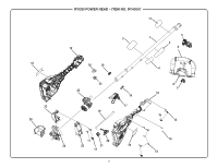
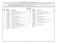
RYOBI POWER HEAD - ITEM NO. RY40007 The item and manufacturing number will be found on a label attached to the boom assembly. Always mention the item and manufacturing number of your POWER HEAD when requesting service or ordering repair parts. PARTS LIST KEY PART KEY PART NO. NUMBER DESCRIPTION QTY NO. NUMBER DESCRIPTION QTY 1 315648001 Upper Boom Assembly (Inc. Key Nos. 2-4 & 11).....1 16 695180001 Compression Spring (Trigger Lock 1 2 941013005 Warning Label (French/Spanish 1 17 313687001 Switch Trigger Assembly w/Lock-Out 1 3 941013004 Warning Icon Label 1 18 534157001 Slide Switch Cover 1 4 941851235 Data Label 1 19 639787001 Rod 1 5 314562001 Boom Clamp Assembly 1 20 760579005 Variable Speed Switch 1 6 308056009 Front Handle Assembly (Inc. Key Nos. 7-9 1 21 534149001 Switch Cap 1 7 518949001 Wing Nut (1/4-20 1 22 313350001 Motor Volute Assembly 1 8 639167001 Assist Handle Clamp 1 23 313240001 Electric Controller and Switch Assembly 1 9 660857001 Screw (1-1/4-20 x 1 in. Square Hd 1 24 534155001 Bucket Housing 1 10 690140011 Compression Spring 1 25 313244001 Motor & Gear Box Assembly 1 11 941851150 Attachment Capable Label 1 12 313242004 Rear Handle Assembly (Inc. Key No. 15 1 13 661864007 Screw (M4 x 18 mm, T15 Torx Pan Hd 14 14 660203052 Screw (M3 x 8 mm, Pan. Hd 2 Not Shown 995000923 1-8-20 (Rev:02) Operator's Manual 15 940705393 Logo Label 2 3

  • 1
  • 2
  • 3
  • 4

RYOBI POWER HEAD – ITEM NO. RY40007
3
The item and manufacturing number will be found on a label attached to the boom assembly. Always mention the item and manufacturing
number of your
POWER HEAD
when requesting service or ordering repair parts.
PARTS LIST
KEY
PART
NO.
NUMBER
DESCRIPTION
QTY
KEY
PART
NO.
NUMBER
DESCRIPTION
QTY
1
315648001
Upper Boom Assembly (Inc. Key Nos. 2-4 & 11)
....
1
2
941013005
Warning Label (French/Spanish)
.............................
1
3
941013004
Warning Icon Label
.................................................
1
4
941851235
Data Label
...............................................................
1
5
314562001
Boom Clamp Assembly
..........................................
1
6
308056009
Front Handle Assembly (Inc. Key Nos. 7-9)
............
1
7
518949001
Wing Nut (1/4-20)
....................................................
1
8
639167001
Assist Handle Clamp
...............................................
1
9
660857001
Screw (1-1/4-20 x 1 in. Square Hd)
........................
1
10
690140011
Compression Spring
...............................................
1
11
941851150
Attachment Capable Label
.....................................
1
12
313242004
Rear Handle Assembly (Inc. Key No. 15)
................
1
13
661864007
Screw (M4 x 18 mm, T15 Torx Pan Hd.).
..............
14
14
660203052
Screw (M3 x 8 mm, Pan. Hd.)
.................................
2
15
940705393
Logo Label
..............................................................
2
16
695180001
Compression Spring (Trigger Lock)
.........................
1
17
313687001
Switch Trigger Assembly w/Lock-Out
.....................
1
18
534157001
Slide Switch Cover
..................................................
1
19
639787001
Rod
..........................................................................
1
20
760579005
Variable Speed Switch
............................................
1
21
534149001
Switch Cap
..............................................................
1
22
313350001
Motor Volute Assembly
...........................................
1
23
313240001
Electric Controller and Switch Assembly
................
1
24
534155001
Bucket Housing
.......................................................
1
25
313244001
Motor & Gear Box Assembly
..................................
1
Not Shown
995000923
Operator's Manual
1-8-20
(Rev:02)