Ryobi RY48ZTR100 Parts Diagram - Page 6
Control Arm Assembly
 |
View all Ryobi RY48ZTR100 manuals
Add to My Manuals
Save this manual to your list of manuals |
Page 6 highlights
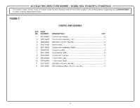
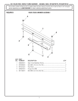
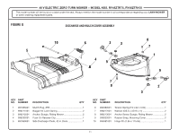
48 V ELECTRIC ZERO TURN MOWER − MODEL NOS. RY48ZTR75, RY48ZTR100 The model number will be found on a label under the seat. Always mention the model number in all correspondence regarding your LAWN MOWER or when ordering replacement parts. FIGURE C CONTROL ARM ASSEMBLY KEY PART NO. NUMBER 1 997045001 2 997144001 3 996046001 4 994771001 5 997145001 6 994867001 7 994770001 8 997072001 9 997043001 10 997044001 11 997135001 12 997146001 DESCRIPTION QTY Control Arm Handle 2 Control Arm Assembly, Left 1 Bolt (M8 x 25 mm, Hex Hd 8 Washer (M8 8 Control Arm Assembly, Right 1 Flange Nut (M8 4 Lock Washer (M8 8 Control Arm Damper 2 T Slot Insert, Left 1 T Slot Insert, Right 1 Bolt (M8 x 35 mm, Hex Hd 4 Bolt w/Washer (M8 x 25 mm, Hex Hd 4 6
-
 1
1 -
 2
2 -
 3
3 -
 4
4 -
 5
5 -
 6
6 -
 7
7 -
 8
8 -
 9
9 -
 10
10 -
 11
11 -
 12
12 -
13
-
14
-
15
-
16
-
17
-
18
-
19
-
20
-
21
-
22
-
23
-
24
-
25
 |
 |

48 V ELECTRIC ZERO TURN MOWER − MODEL NOS. RY48ZTR75, RY48ZTR100
6
The model number will be found on a label under the seat. Always mention the model number in all correspondence regarding your
LAWN MOWER
or when ordering replacement parts.
1
997045001
Control Arm Handle
.........................................................................
2
2
997144001
Control Arm Assembly, Left
.............................................................
1
3
996046001
Bolt (M8 x 25 mm, Hex Hd.)
............................................................
8
4
994771001
Washer (M8)
.....................................................................................
8
5
997145001
Control Arm Assembly, Right
...........................................................
1
6
994867001
Flange Nut (M8)
...............................................................................
4
7
994770001
Lock Washer (M8)
............................................................................
8
8
997072001
Control Arm Damper
........................................................................
2
9
997043001
T Slot Insert, Left
.............................................................................
1
10
997044001
T Slot Insert, Right
...........................................................................
1
11
997135001
Bolt (M8 x 35 mm, Hex Hd.)
............................................................
4
12
997146001
Bolt w/Washer (M8 x 25 mm, Hex Hd.)
...........................................
4
KEY
PART
NO.
NUMBER
DESCRIPTION
QTY
CONTROL ARM ASSEMBLY
FIGURE C