Ryobi RYI2200 User Manual 2 - Page 11
Wiring Diagram - oil
 |
View all Ryobi RYI2200 manuals
Add to My Manuals
Save this manual to your list of manuals |
Page 11 highlights
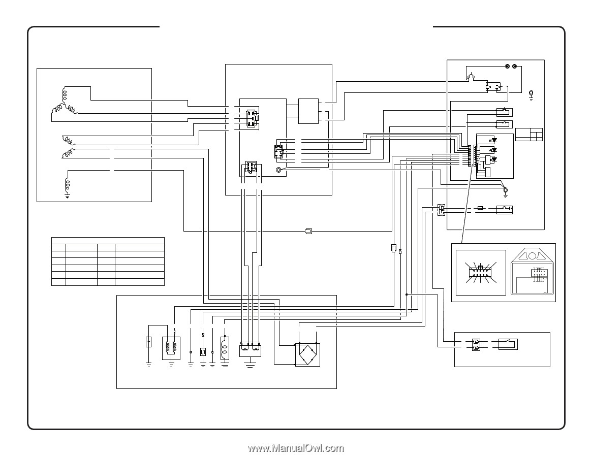
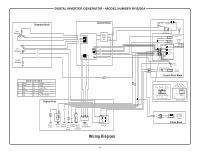
DIGITAL INVERTER GENERATOR - MODEL NUMBER RYi2200A Sub Winding Generator Block DC Winding B B R Exciter Winding Inverter Block B r B r B r O O BP Y O Noise W Filter G (AC) W G r B l W B r R R G / Y WIRES COLOR CODES G Green W White O Orange BI Black B Blue Y Yellow R Red P Pink Lb Light Blue Br Brown Gr Gray G / Y Green / Yellow Engine Block B G/Y O BI BI R B I Spark Plug Ignition Coil Engine Ground Oil Level Engine Ignition Ground Pulse Throttle Control Motor Switch Generator Rectifier Wiring Diagram 11 20A CB Parallel Connectors Ground G / Y Terminal 120V / 20 A Duplex Receptacle Reset push button (Normally Open) Press to remove overload condition Output Indicator "G" Intelligent Throttle Switch Switch Position ON OFF Intelligent Throttle OFF ON Overload Indicator "R" R Lb B I Low Oil B I O Indicator "O" B Ignition Module In line Fuse (10 A) R R B I Frame Ground DC Output Receptacle Control Panel Block 10 orange 98 red black 7 light blue 6 blue black grey brown white black 54 3 2 1 Harness Connector 109 876 5432 1 Ignition Module R R B I B I Engine On / Off Switch Frame Block
-
 1
1 -
2
-
3
-
4
-
5
-
 6
6 -
 7
7 -
 8
8 -
 9
9 -
 10
10 -
 11
11
 |
 |