Ryobi TR45K English Manual - Page 19
Brush Replacement
 |
View all Ryobi TR45K manuals
Add to My Manuals
Save this manual to your list of manuals |
Page 19 highlights
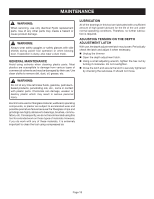
MAINTENANCE BRUSH REPLACEMENT See Figures 14 - 15. n Unplug the trimmer. n Remove screws from the top cover of the trimmer. n Remove the top cover. n Remove the clamp screws. n Remove the brush tube clamps. n Disconnect the red and black lead terminals from the brush tubes. n Replace the brush assemblies. n Reconnect the red and black lead terminals to the brush tubes. n Ensure that the wires are placed securely in the lead traps to prevent loose wires. n Replace the brush tube clamps and clamp screws. n Replace the top cover. n Replace the screws on the top cover of the trimmer. n Tighten all screws securely. Do not overtighten. SCREWS TOP COVER LEADTRAP LEADTRAP CLAMP SCREWS BRUSH TUBE CLAMPS BLACK LEAD BRUSH ASSEMBLY RED LEAD RED LEAD BLACK LEAD BRUSH ASSEMBLY Fig. 14 n Remove the brush assemblies. n Check for wear. Replace both brush assemblies when either has less than 1/4 in. length of carbon remaining. Do not replace one side without replacing the other. n Make sure the wire terminals are secured to the brush tubes prior to reassembly. n Reassemble using new brush assemblies. Make sure the curvature of the brush matches the curvature of the motor and that the brush moves freely in the brush tube. Page 19 LEAD TERMINAL BRUSH TUBE BRUSH Fig. 15
-
 1
1 -
2
-
3
-
4
-
5
-
6
-
7
-
8
-
9
-
10
-
11
-
12
-
13
-
 14
14 -
 15
15 -
 16
16 -
 17
17 -
 18
18 -
 19
19 -
 20
20
 |
 |
