Ryobi TS1346 Operation Manual - Page 14
Caution, Warning
 |
View all Ryobi TS1346 manuals
Add to My Manuals
Save this manual to your list of manuals |
Page 14 highlights
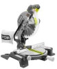
ASSEMBLY CAUTION: Always install the blade with the blade teeth and the arrow printed on the side of the blade pointing down at the front of the saw. The direction of blade rotation is also stamped with an arrow on the upper blade guard. I Tighten blade bolt securely. I Replace the lower blade guard and blade bolt cover. I Replace screw B and tighten securely. I Retighten screw A securely. WARNING: Make sure the spindle lock button is not engaged before reconnecting saw into power source. Never engage spindle lock button when blade is rotating. Note: Many of the illustrations in this manual show only portions of your compound miter saw. This is intentional so that we can clearly show points being made in the illustrations. Never operate your saw without all guards securely in place and in good operating condition. SQUARING THE MITER TABLE TO THE FENCE See Figures 13 - 16. I Unplug your saw. FRAMING SQUARE MITER FENCE MITER TABLE Your compound miter saw has been adjusted at the factory for making very accurate cuts. However, some of the components might have been jarred out of alignment during shipping. Also, over a period of time, readjustment will probably become necessary due to wear. After unpacking your saw, check the following adjustments before you begin using saw. Make any readjustments that are necessary and periodically check the parts alignment to make sure that your saw is cutting accurately. WARNING: Your saw should never be connected to power supply when you are assembling parts, making adjustments, installing or removing blades, or when not in use. Disconnecting your saw will prevent accidental starting that could cause serious injury. 45 31.6 30 15 1 5 22.5 45 31.6 30 MITER LOCK PLATE ZERO CLEARANCE THROAT PLATE MITER LOCK HANDLE VIEW OF MITER TABLE SQUARE WITH FENCE Fig. 13 Page 14
-
 1
1 -
2
-
3
-
4
-
5
-
6
-
7
-
8
-
 9
9 -
 10
10 -
 11
11 -
 12
12 -
 13
13 -
 14
14 -
 15
15 -
 16
16 -
 17
17 -
 18
18 -
 19
19 -
20
-
21
-
22
-
23
-
24
-
25
-
26
-
27
-
28
 |
 |
