Ryobi TS1355LA English Manual - Page 31
Depth Stop, Depth Stop Adjustments, Positive Stop Adjustments
 |
View all Ryobi TS1355LA manuals
Add to My Manuals
Save this manual to your list of manuals |
Page 31 highlights
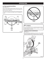
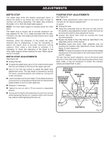
ADJUSTMENTS DEPTH STOP The depth stop limits the blade's downward travel. It allows the blade to go below the miter table enough to maintain full cutting capacities. The depth stop positions the blade 1/4 in. from the miter table support. NOTE: The miter table support is located inside the miter table. The depth stop is factory set to provide maximum cutting capacity for the 10 in. blade provided with the saw. Therefore, the saw with blade provided should never need adjustments. However, when the diameter of the blade has been reduced due to sharpening, it may be necessary to adjust the depth stop to provide maximum cutting capacity. Also, when a new blade is installed, it is necessary to check the clearance of the blade to the miter table support before starting the saw. Make adjustments if needed. DEPTH STOP ADJUSTMENTS See Figure 44. Unplug the saw. To adjust the depth stop use a 10 mm wrench and loosen the hex nut located on the top of the upper saw arm. Use a 5 mm hex key wrench to adjust the depth stop adjustment screw. The saw blade is lowered by turning the screw counterclockwise and raised by turning the screw clockwise. Lower the blade into the miter table. Check blade clearance and maximum cutting distance (distance from fence where blade enters) to front of miter table slot. Readjust if necessary. Tighten the hex nut with a 10 mm wrench or adjustable wrench. To prevent the depth stop adjustment screw from turning while tightening the hex nut, carefully hold it with the hex key wrench while tightening the hex nut. POSITIVE STOP ADJUSTMENTS See Figure 44. NOTE: These adjustments were made at the factory and normally do not require readjustment. To adjust: Unplug the saw. Using two wrenches (one on the lock nut and one for the positive stop adjustment screw), loosen the lock nut securing the positive stop adjustment screw. Loosen the bevel lock knob by turning the knob counterclockwise. Square the blade to the miter table as described in the Assembly section of this manual. Retighten bevel lock knob. Next, retighten lock nut securing the positive stop adjustment screw. Recheck blade-to-table alignment. NOTE: The above procedure can be used to check blade squareness of the saw blade to the miter table at both 0° and 45° angles. The saw has two scale indicators, one on the bevel scale and one on the miter scale. After squaring adjustments have been made, it may be necessary to loosen the indicator screws and reset them to zero. DEPTH STOP ADJUSTMENT SCREW POSITIVE STOP ADJUSTMENT SCREW FOR 0° ANGLES BEVEL LOCK KNOB POSITIVE STOP ADJUSTMENT SCREW FOR 45° ANGLES LOCK NUT(S) Fig. 44 31
-
 1
1 -
2
-
3
-
4
-
5
-
6
-
7
-
8
-
9
-
10
-
11
-
12
-
13
-
14
-
15
-
16
-
17
-
18
-
19
-
20
-
21
-
22
-
23
-
24
-
25
-
 26
26 -
 27
27 -
 28
28 -
 29
29 -
 30
30 -
 31
31 -
 32
32 -
 33
33 -
 34
34
 |
 |
