Samsung 5065W User Manual (user Manual) (ver.1.0) (English) - Page 27
Connecting to R, G, B, the TV and the R.G.B OUT
 |
View all Samsung 5065W manuals
Add to My Manuals
Save this manual to your list of manuals |
Page 27 highlights
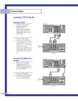
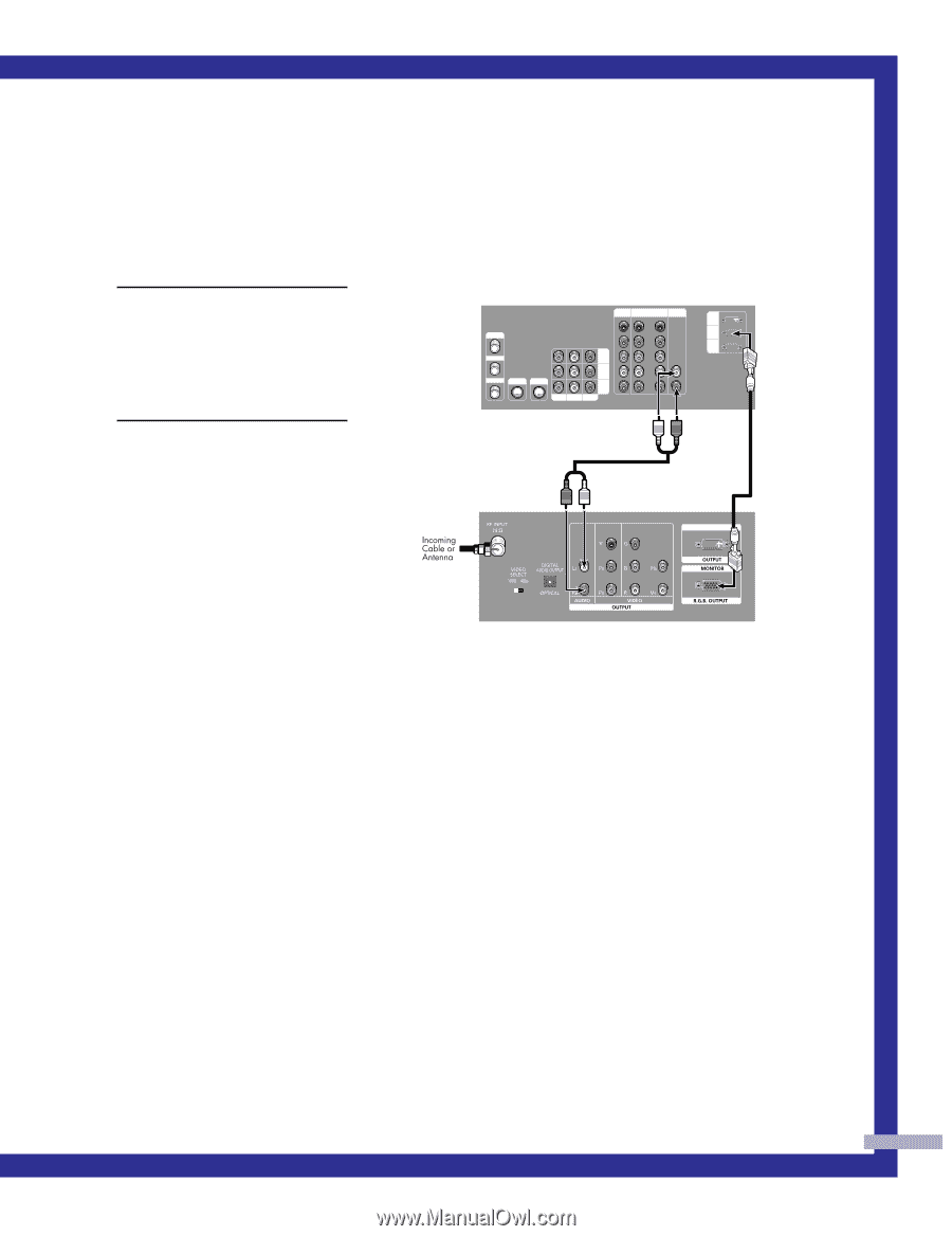
Connecting to R,G,B 1 Connect a set of audio cables between the PC AUDIO IN jacks on the TV and the AUDIO OUT jacks on the Set Top Box. 2 Connect video cables between the PC IN jack on the TV and the R.G.B OUT jack on the Set Top Box. TV Rear Panel Component1 Component1/2 (480i/480p) (480p/720p/10801i) PC AUDIO Y ANT-A Pb ANT A-OUT MONITOR OUT Pr VIDEO 2 L L ANT-B S-VIDEO 1 S-VIDEO 2 VIDEO 1 R R V L R DVI PC RS-232C DVI DTV Set Top Box 27
-
 1
1 -
2
-
3
-
4
-
5
-
6
-
7
-
8
-
9
-
10
-
11
-
12
-
13
-
14
-
15
-
16
-
17
-
18
-
19
-
20
-
21
-
 22
22 -
 23
23 -
 24
24 -
 25
25 -
 26
26 -
 27
27 -
 28
28 -
 29
29 -
 30
30 -
 31
31 -
 32
32 -
33
-
34
-
35
-
36
-
37
-
38
-
39
-
40
-
41
-
42
-
43
-
44
-
45
-
46
-
47
-
48
-
49
-
50
-
51
-
52
-
53
-
54
-
55
-
56
-
57
-
58
-
59
-
60
-
61
-
62
-
63
-
64
-
65
-
66
-
67
-
68
-
69
-
70
-
71
-
72
-
73
-
74
-
75
-
76
-
77
-
78
-
79
-
80
-
81
-
82
-
83
-
84
-
85
-
86
-
87
-
88
 |
 |
27
Connecting to R,G,B
1
Connect a set of audio
cables between the PC
AUDIO IN jacks on the TV
and the AUDIO OUT jacks
on the Set Top Box.
2
Connect video cables
between the PC IN jack on
the TV and the R.G.B OUT
jack on the Set Top Box.
Component1
(480i/480p)
Component1/2
(480p/720p/10801i)
Y
P
b
P
r
L
R
L
R
PC AUDIO
DTV Set Top Box
ANT-A
ANT A-OUT
ANT-B
S-VIDEO 1
S-VIDEO 2
V
L
R
MONITOR
OUT
VIDEO
2
VIDEO
1
DVI
PC
RS-232C
TV Rear Panel
DVI