Samsung HT-Q100 Quick Guide (easy Manual) (ver.1.0) (English) - Page 11
Connecting External Components, Connecting the FM Antenna - dvd
 |
View all Samsung HT-Q100 manuals
Add to My Manuals
Save this manual to your list of manuals |
Page 11 highlights
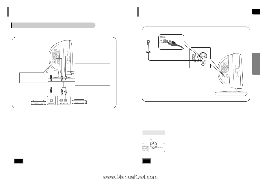
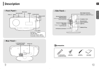
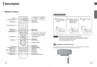
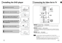
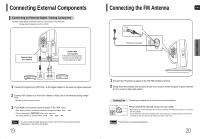
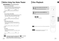
Connecting External Components Connecting the FM Antenna ENG Connecting an External Digital / Analog Component Example: Digital signal components such as a Set-Top Box or CD Recorder. Analog signal components such as a VCR. CONNECTIONS Optical Cable (not supplied) Audio Cable (not supplied) If the external analog component has only one Audio Out, connect either left or right. FM Antenna (supplied) 1 Connect the Digital Input (OPTICAL) to the Digital Output on the external digital component. 2 Connect AUX (Audio) In on the Home Theater to Audio Out on the external analog component. • Be sure to match connector colors. 3 Press AUX on the remote control to select 'D.IN / AUX' input. • Each time the button is pressed, the selection changes as follows: D.IN ➝ AUX • You can also use the FUNCTION button on the main unit. The mode switches as follows: DVD ➝ D.IN ➝ AUX ➝ USB ➝ FM Note • You can connect the Video Output jack on your VCR to the TV, and connect the Audio Output jacks on the VCR to this product. 19 1 Connect the FM antenna supplied to the FM 75Ω COAXIAL terminal. 2 Slowly move the antenna wire around until you find a location where reception is good, then fas- ten it to a wall or other rigid surface. Cooling Fan The cooling fan supplies cool air to the unit to prevent overheating. Please observe the following cautions for your safety. • Make sure the unit is well-ventilated. If the unit has poor ventilation, the temperature inside the unit could rise and may damage it. • Do not obstruct the cooling fan or ventilation holes. (If the cooling fan or ventilation holes are covered with a newspaper or cloth, heat may build up inside the unit and fire may result.) Notes • This unit does not receive AM broadcasts. 20
-
 1
1 -
2
-
3
-
4
-
5
-
 6
6 -
 7
7 -
 8
8 -
 9
9 -
 10
10 -
 11
11 -
 12
12 -
 13
13 -
 14
14 -
 15
15 -
 16
16 -
17
-
18
-
19
-
20
-
21
-
22
-
23
-
24
-
25
-
26
-
27
-
28
-
29
-
30
-
31
-
32
-
33
-
34
-
35
 |
 |