Samsung MC17J8000C Installation Guide - Page 10
D. ALIGNING THE WALL PLATE, Holes A, B and C are inside area E. If none
 |
View all Samsung MC17J8000C manuals
Add to My Manuals
Save this manual to your list of manuals |
Page 10 highlights
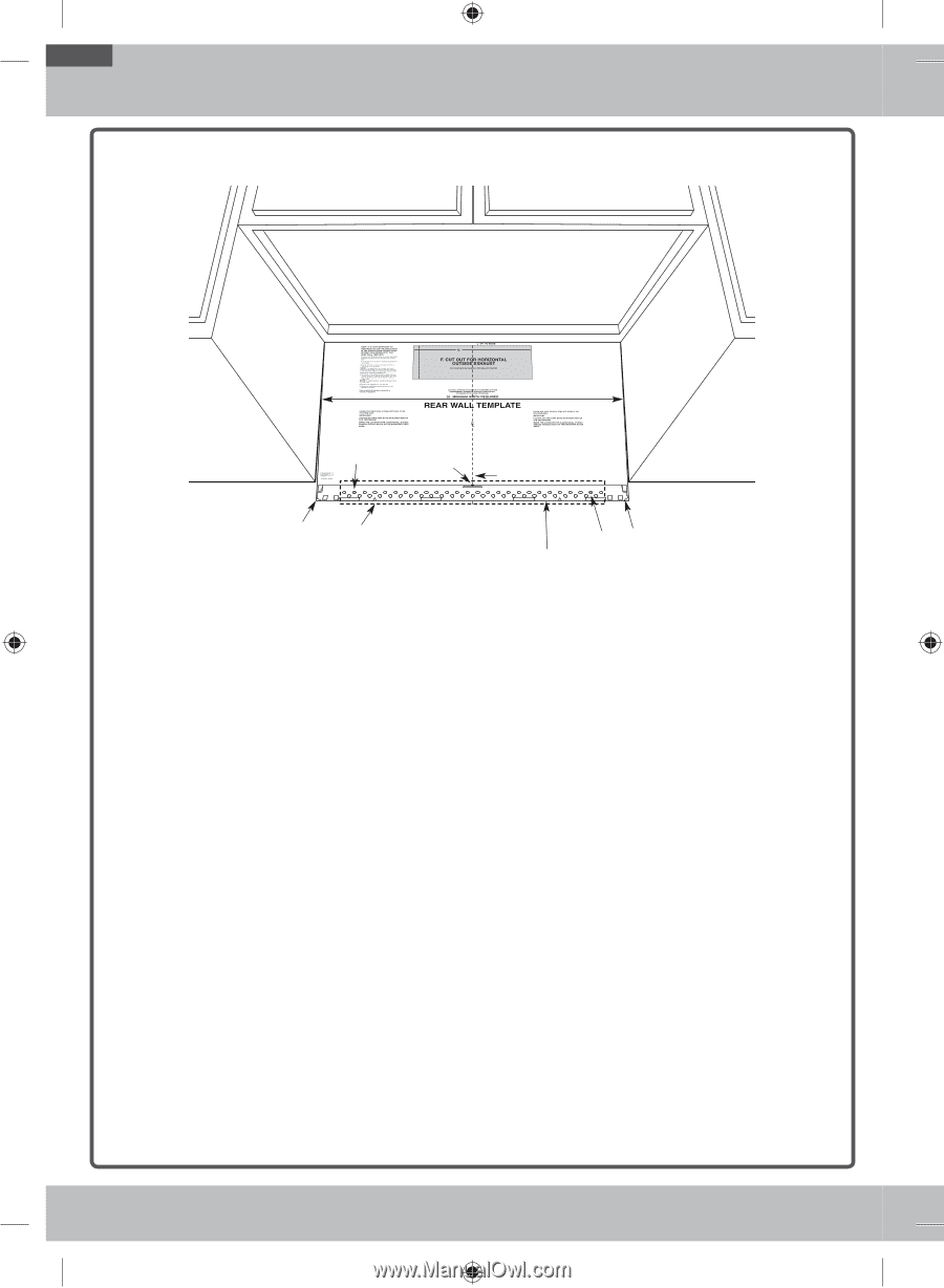
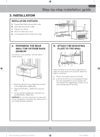
Step-by-step installation guide D. ALIGNING THE WALL PLATE HHooleleAA CCeenntteerrllininee nnoottcchheess DDrraw a VHeorrtizcoalnLtainleline on tooohfnfe"TWRwoepaaallCllrfaarWoblomiannlelgCtTetehnmetepbrloattteo".m CL HoHroizrioznontatal lLLiinnee AArrea E CAUTION: Wear gloves to avoid cutting CAUTIfiOngNe:rsWoneasrhagrlpoveedsgetso. avoid cutting fingers on sharp edges. Hole B Hoorriizzoonntatal Ll iLniene DDrraawwaaHHoroizroiznotanltlainlelionnewoanll wfroamll fbrootmtom of "Rear bWoatltloTmemopflat"eR".ear Wall Template". 1. Draw a Horizontal line on the wall at the bottom of the "Rear Wall Template". 2. Drill ⅝˝ holes for toggle bolts in 3 locations (Hole A, Hole B, Hole C) as shown in the illustration above. If the location of a hole lines up with a stud, drill a 3/16˝ hole for a wood screw. You cannot use a toggle bolt to attach the wall plate to a stud. NOTE: DO NOT MOUNT THE PLATE AT THIS TIME. 3. Holes A, B and C are inside area E. If none of these holes line up with a stud, find a stud in area E that lines up with a hole circle in Area E, and then drill a 3/16˝ hole into it for a wood screw. You must have at least one wood screw mounted firmly into a stud to support the weight of the microwave. Set the mounting plate aside. 10 Installation_MC17J8100CS_AA_DE68-04129C-01_EN+MES.indb 10 2017-10-19 6:42:01
-
 1
1 -
2
-
3
-
4
-
 5
5 -
 6
6 -
 7
7 -
 8
8 -
 9
9 -
 10
10 -
 11
11 -
 12
12 -
 13
13 -
 14
14 -
 15
15 -
16
-
17
-
18
-
19
-
20
-
21
-
22
-
23
-
24
-
25
-
26
-
27
-
28
-
29
-
30
-
31
-
32
-
33
-
34
-
35
-
36
-
37
-
38
-
39
-
40
 |
 |