Samsung NX58K3310SS/AA Installation Guide - Page 21
English 21
 |
View all Samsung NX58K3310SS/AA manuals
Add to My Manuals
Save this manual to your list of manuals |
Page 21 highlights
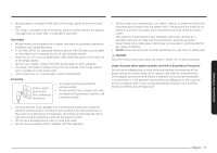
Never use an old connector when installing a new range. If the hard-piping method is used, you must carefully align the pipe; the range cannot be moved after the connection is made. To prevent gas leaks, apply pipe-joint compound or wrap pipe-thread tape with Teflon on all male (external) pipe threads. 1. Install a manual gas line shut-off valve in the gas line in an easily accessed location outside of the range. Make sure everyone operating the range knows where and how to shut off the gas supply to the range. 2. Install male 0.5-in (1.3-mm) flare union adapter to the 0.5-in (1.3-mm) NPT internal thread at the regulator inlet. Use a backup wrench on the regulator fitting to avoid damage. When installing the range from the front, remove the 90 ° elbow for easier installation. 3. Install male 0.5-in (1.3-mm) or 0.75-in (1.9-mm) flare union adapter to the NPT internal thread of the manual shut-off valve, taking care to back up the shut-off valve to keep it from turning. 4. Connect flexible metal appliance connector to the adapter on the range. Position range to permit connection at the shut-off valve. 5. When all connections have been made, make sure all range controls are in the off position and turn on the main gas supply valve. Use a liquid leak detector at all joints and connections to check for leaks in the system. WARNING Do not use a flame to check for gas leaks to prevent death, personal injury, explosion, and/or fire hazard. When using test pressures greater than 1/2 psig to pressure-test the gas supply system of the residence, disconnect the range and individual shut-off valve from the gas supply piping. When using test pressures of 1/2 psig or less to test the gas supply system, simply isolate the range from the gas supply system by closing the individual shut-off valve. Flexible connector hookup Installer: Inform the consumer of the location of the gas shut-off valve. Gas Flow into Range Gas Shut-Off Valve 0.5-in or 0.75-in Gas Pipe Adapter Tubing Line to Oven Burner Control Valve Flex Connector (6-ft max.) Tubing Line to Cooktop Control Manifold Adapter Pressure Regulator NOTE If your area requires a rigid pipe hookup, contact a qualified installer, service agency, or gas supplier. NOTE The gas shut-off valve should be installed in an accessible location in the gas piping, external to the appliance, for the purpose of turning on or shutting off the gas to the appliance. Installation instructions English 21
-
 1
1 -
2
-
3
-
4
-
5
-
6
-
7
-
8
-
9
-
10
-
11
-
12
-
13
-
14
-
15
-
 16
16 -
 17
17 -
 18
18 -
 19
19 -
 20
20 -
 21
21 -
 22
22 -
 23
23 -
 24
24 -
 25
25 -
 26
26 -
27
-
28
-
29
-
30
-
31
-
32
-
33
-
34
-
35
-
36
-
37
-
38
-
39
-
40
-
41
-
42
-
43
-
44
-
45
-
46
-
47
-
48
-
49
-
50
-
51
-
52
-
53
-
54
-
55
-
56
-
57
-
58
-
59
-
60
-
61
-
62
-
63
-
64
-
65
-
66
-
67
-
68
-
69
-
70
-
71
-
72
-
73
-
74
-
75
-
76
-
77
-
78
-
79
-
80
-
81
-
82
-
83
-
84
 |
 |
