Samsung SGH E250 Service Manual - Page 19
Disassemble FPCB after lifting Connector
 |
View all Samsung SGH E250 manuals
Add to My Manuals
Save this manual to your list of manuals |
Page 19 highlights
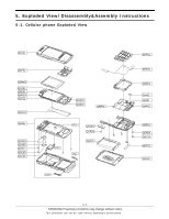
Exploded View/Disassembly&Assembly Instructions 9 1) Unscrew 4 screws 2) Disassemble the upper with a couple of thumbs pressing the point of picture 10 1) Match the hole of LOWER and FRONT holding up the slide 2) Draw out the FPCB from the hole 1) Be careful of body damage and scretch 1) Be careful of cutting wire 2) Be careful of body damage and scretch 11 1) Remove the tape covering FPCB Connector 2) Disassemble FPCB after lifting Connector 12 1) Disassemble Speaker, Motor 2) Remove the tape on the Camera Connector 3) Disassemble the Camera taking down the top of the camera 1) Be careful of body damage and scretch 2) Be careful of damaging F-PCB 1) Be careful of body damage and scretch 2) Be careful of damaging camera F-PCB 5-6 SAMSUNG Proprietary-Contents may change without notice This Document can not be used without Samsung's authorization
-
 1
1 -
2
-
3
-
4
-
5
-
6
-
7
-
8
-
9
-
10
-
11
-
12
-
13
-
 14
14 -
 15
15 -
 16
16 -
 17
17 -
 18
18 -
 19
19 -
 20
20 -
 21
21 -
 22
22 -
 23
23 -
 24
24 -
25
-
26
-
27
-
28
-
29
-
30
-
31
-
32
-
33
-
34
-
35
-
36
-
37
-
38
-
39
-
40
-
41
-
42
-
43
-
44
-
45
-
46
-
47
-
48
-
49
-
50
-
51
-
52
-
53
-
54
-
55
-
56
-
57
-
58
-
59
-
60
-
61
-
62
-
63
-
64
-
65
-
66
-
67
-
68
-
69
-
70
 |
 |
