Samsung SHR-5082 User Manual - Page 9
Rear Panel Jacks
 |
View all Samsung SHR-5082 manuals
Add to My Manuals
Save this manual to your list of manuals |
Page 9 highlights
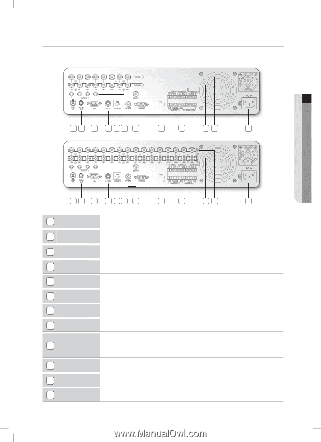
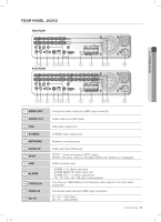
REAR PANEL JACKS 5082 REAR 01 INTRODUCING 12 3 4 56 7 8 9 10 11 12 5162 REAR 12 3 4 56 7 8 9 10 11 12 1 VIDEO OUT 2 AUDIO OUT 3 VGA 4 S-VIDEO 5 NETWORK 6 AUDIO IN 7 SPOT 8 USB 9 ALARM 10 THROUGH 11 VIDEO IN 12 AC-IN Composite video output port (BNC type connector) Audio output port (RCA jack) aVGA video output port S-VIDEO video output port Network connection port Audio input port (RCA jack) SPOT1: 1 channel exclusive SPOT output SPOT2: The same output as the Main VIDEO OUT (OSG is not displayed) USB connection port - ALARM 1-16: Alarm input port - ALARM RESET IN: Alarm reset port - ALARM OUT 1-4: Alarm output port - TX+, TX-, RX+, RX-: RS-485 communication You may use THROUGH port to transmit a video signal to the other video equipment. Composite video input port (BNC type connector) AC 100 ~ 230V (PAL) AC 110 ~ 220V (NTSC) introducing _05 SHR-5162_Eng.indb 5 2007-06-18 11:47:07
-
 1
1 -
2
-
3
-
 4
4 -
 5
5 -
 6
6 -
 7
7 -
 8
8 -
 9
9 -
 10
10 -
 11
11 -
 12
12 -
 13
13 -
 14
14 -
15
-
16
-
17
-
18
-
19
-
20
-
21
-
22
-
23
-
24
-
25
-
26
-
27
-
28
-
29
-
30
-
31
-
32
-
33
-
34
-
35
-
36
-
37
-
38
-
39
-
40
-
41
-
42
-
43
-
44
-
45
-
46
-
47
-
48
-
49
-
50
-
51
-
52
-
53
-
54
-
55
-
56
-
57
-
58
-
59
-
60
-
61
-
62
-
63
-
64
-
65
-
66
-
67
-
68
-
69
-
70
-
71
-
72
-
73
-
74
-
75
-
76
-
77
-
78
-
79
-
80
-
81
-
82
-
83
-
84
-
85
-
86
-
87
-
88
-
89
-
90
-
91
-
92
-
93
 |
 |