Samsung SRP-270AP Operation Manual - Page 30
Interface Connector
 |
View all Samsung SRP-270AP manuals
Add to My Manuals
Save this manual to your list of manuals |
Page 30 highlights
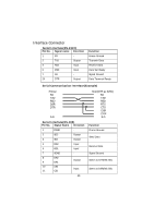
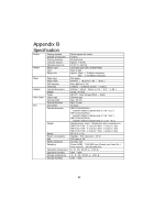
Interface Connector Serial Interface(RS-232C) Pin No. Signal name Direction 1 FG - 2 TxD Output 3 RxD Input 6 DSR Input 7 SG - 20 DTR Output Function Frame Ground Transmit Data Receive Data Data Set Ready Signal Ground Data Terminal Ready Serial Communication Interface(Example) Printer SG TXD RSD DSR DTR S.G Host(DTE ex 8251) SG TXD RSD RTS CTS DSR DTR S.G Serial Interface(RS-485) Pin No. Signal Name Direction 1 FGND - 2 SD2 Output 3 SD1 Output 4 RD2 Input 5 RD1 Input 7 SGND - 8 DR2 9 DR1 Output 10 CS2 11 CS1 Input Function Frame Ground Send Data Receive Data Signal Ground Same as DTR(RS-232) Same as DSR(RS-232) 30
-
 1
1 -
2
-
3
-
4
-
5
-
6
-
7
-
8
-
9
-
10
-
11
-
12
-
13
-
14
-
15
-
16
-
17
-
18
-
19
-
20
-
21
-
22
-
23
-
24
-
 25
25 -
 26
26 -
 27
27 -
 28
28 -
 29
29 -
 30
30 -
 31
31 -
 32
32 -
 33
33 -
 34
34 -
 35
35 -
36
 |
 |

30
Interface Connector
Serial Interface(RS-232C)
Pin No.
Signal name
Direction
Function
1
FG
-
Frame Ground
2
TxD
Output
Transmit Data
3
RxD
Input
Receive Data
6
DSR
Input
Data Set Ready
7
SG
-
Signal Ground
20
DTR
Output
Data Terminal Ready
Serial Communication Interface(Example)
Printer
Host(DTE ex 8251)
SG
SG
TXD
TXD
RSD
RSD
DSR
RTS
DTR
CTS
DSR
DTR
S.G
S.G
Serial Interface(RS-485)
Pin No.
Signal Name
Direction
Function
1
FGND
-
Frame Ground
2
SD2
Output
3
SD1
Output
Send Data
4
RD2
Input
5
RD1
Input
Receive Data
7
SGND
-
Signal Ground
8
9
DR2
DR1
Output
Same as DTR(RS-232)
10
11
CS2
CS1
Input
Same as DSR(RS-232)