Samsung TXK3276 Service Manual - Page 29
Troubleshooting - remote control
 |
View all Samsung TXK3276 manuals
Add to My Manuals
Save this manual to your list of manuals |
Page 29 highlights
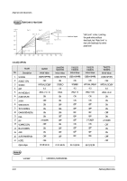
5. Troubleshooting 5-1 No Power Samsung Electronics Plug in Power Cord Abnormal ON Check MICOM IIC #5, #6 Normal Check LED lamp Check Level Shifter Q909, Q910 Output(If 2N7000 Output has the DC Component over 0.7V, it is broken) Normal Abnormal Check MICOM IIC #2, #3 Normal Check IC902 EEPROM Normal Check IC201S Abnormal Replace EEPROM(IC902) Replace Q909, Q910 Normal Check the MICOM Power #59 With Remote Controller Normal Replace Q908 Abnormal Replace Q908 Normal Check IC802, IC803 Normal Check IC201S VDP H-OUT #50 Normal Check Q401 H-TR Normal Check 135V Line Normal Replace FBT Abnormal Abnormal Abnormal Abnormal Replace IC802, IC803 Replace IC201S Replace Q401 Check PC801S, IC801S Abnormal Replace the MICOM OFF Abnormal Check IC903 3.3V Regulator Input Voltage Check IC901 MICOM Input Voltage Normal Normal Check and Replace the MICOM Check and Replace IC903 Abnormal Check D801 and D811 Abnormal Normal Replace D801 or D811 Check IC804 Input Voltage Abnormal Check R828 and D805 Normal Normal Check and Replace IC804 Check and Replace R828 or D805 Abnormal Check IC801S and FP801S Troubleshooting Note : When you check whether any component is normal, you must let the output pin be open in order not to be affected by the side of output. 5-1
-
 1
1 -
2
-
3
-
4
-
5
-
6
-
7
-
8
-
9
-
10
-
11
-
12
-
13
-
14
-
15
-
16
-
17
-
18
-
19
-
20
-
21
-
22
-
23
-
 24
24 -
 25
25 -
 26
26 -
 27
27 -
 28
28 -
 29
29 -
 30
30 -
 31
31 -
 32
32 -
 33
33 -
 34
34 -
35
-
36
-
37
-
38
-
39
-
40
-
41
-
42
-
43
-
44
-
45
-
46
-
47
-
48
-
49
-
50
-
51
-
52
-
53
-
54
-
55
-
56
-
57
-
58
-
59
-
60
-
61
-
62
-
63
-
64
-
65
-
66
-
67
-
68
-
69
-
70
-
71
-
72
 |
 |
