Sanyo DP26648 Owners Manual - Page 6
Getting Started-controls And Jacks - no picture
 |
View all Sanyo DP26648 manuals
Add to My Manuals
Save this manual to your list of manuals |
Page 6 highlights
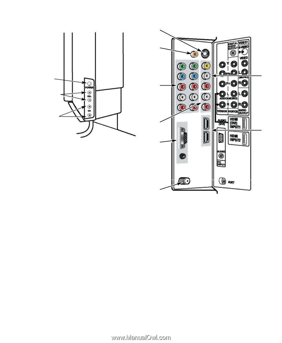
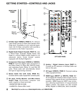
GETTING STARTED-CONTROLS AND JACKS Œ RIGHT-SIDE PANEL Power key ’ Ž Volume - + keys Channel ML keys “ Œ S-Video Input (VIDEO1), PAGE 8-To enhance video detail use the S-Video jack instead of the Video jack, if available on your external equip- ment. (An S-Video connection will override a connection to the Video1 input jack.) Digital Audio Output (Coaxial), PAGE 10-Use a Phono-Type (Coaxial) Digital Audio Out ‘ Cable to connect Digital Audio Output to an advanced stereo home theater system equipped with Dolby® Digital 5.1. LEFT-SIDE PANEL Ž Component Video Input (VIDEO2 or VIDEO3), PAGE 8-Connect digital video equipment to the Video Green (Y), Blue (Pb), Red (Pr) jacks, and matching Audio White (L ) and Red (R) jacks. These jacks will automatically detect the type of signal being received. Stereo Audio Out (L/R) Jacks, PAGE 10- Connect stereo audio equipment to these jacks. PC Input (15-Pin Monitor and Mini Stereo Audio) Page 11-Connect computer and audio outputs to these terminals. • MONITOR RGB (D-SUB) • AUDIO R/L (Stereo Mini Jack) ‘ Analog / Digital Antenna Input, PAGE 5- Connect an RF antenna or Analog Cable system to this jack. ’ AV Input (VIDEO1), PAGE 8-Connect analog video equipment here. “ HDMI Input (INPUT1 or INPUT2), PAGE 10- An all digital AV interface that accepts uncompressed video signals for the very best picture possible. HDMI supports HDCP copy protection, allowing transmission of copy-protected digital content. The signal can also include Dolby® Digital or PCM audio, when available. 6 Need help? Visit our Web site at www.sanyoctv.com or Call 1-800-877-5032
-
 1
1 -
 2
2 -
 3
3 -
 4
4 -
 5
5 -
 6
6 -
 7
7 -
 8
8 -
 9
9 -
 10
10 -
 11
11 -
 12
12 -
13
-
14
-
15
-
16
-
17
-
18
-
19
 |
 |