Schwinn Classic 3 Schwinn Owner's Manual - Page 56
Crank Set
 |
View all Schwinn Classic 3 manuals
Add to My Manuals
Save this manual to your list of manuals |
Page 56 highlights
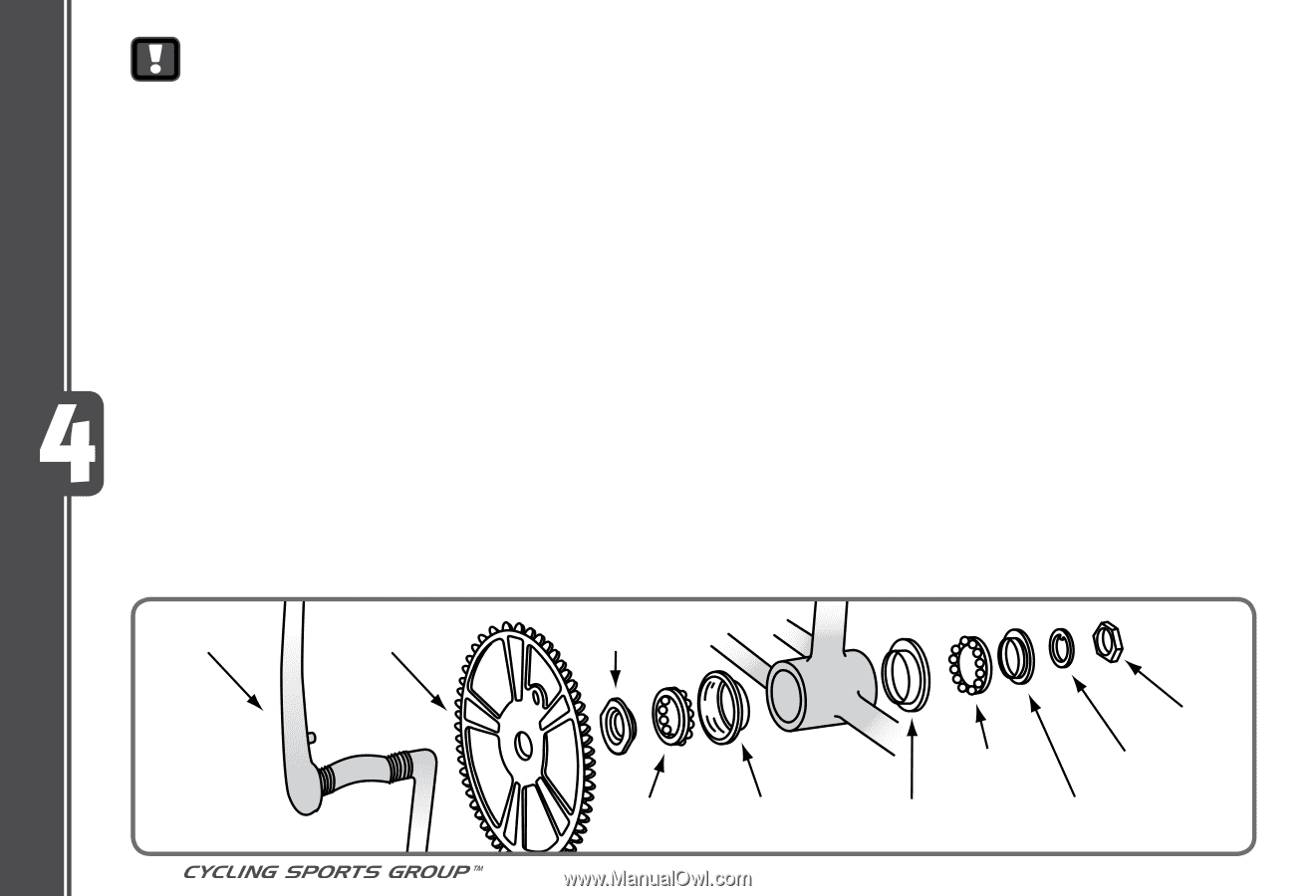
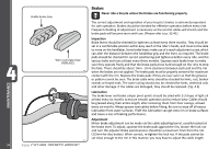
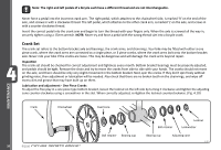
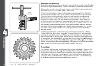
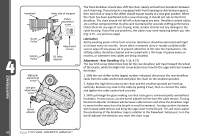
Note: The right and left pedals of a bicycle each have a different thread and are not interchangeable. Never force a pedal into the incorrect crank arm. The right pedal, which attaches to the chainwheel side, is marked 'R' on the end of the axle, and screws in with a clockwise thread. The left pedal, which attaches to the other crank arm, is marked 'L' on the axle, and screws in with a counter-clockwise thread. Insert the correct pedal into the crank arm and begin to turn the thread with your fingers only. When the axle is screwed all the way in, securely tighten using a 15mm wrench. NOTE: Never try and force a pedal with the wrong thread size into a bicycle crank. Crank Set The crank set refers to the bottom bracket axle and bearings, the crank arms, and chainrings. Your bike may be fitted with either a one piece crank, where the crank arms are connected as a single piece, or 3 piece cranks, where the crank arms bolt onto the bottom bracket axle. Never ride your bike if the cranks are loose. This may be dangerous and will damage the crank arms beyond repair. Inspection The crank set should be checked for correct adjustment and tightness every month. Bottom bracket bearings must be properly adjusted, and pedals should be tight. Remove the chain and try to move the cranks from side to side with your hands. The cranks should not move on the axle, and there should be only very slight movement in the bottom bracket. Next, spin the cranks. If they don't spin freely without grinding noise, then adjustment or lubrication will be needed. Also check that there are no broken teeth on the chainrings, and wipe off excess dirt and grease that may have built up on them. Lubrication and adjustment - One Piece Cranks To adjust the free play in a one piece type bottom bracket, loosen the locknut on the left side by turning it clockwise and tighten the adjusting cone counter-clockwise using a screwdriver in the slot. When correctly adjusted, re-tighten the locknut counterclockwise. (Fig. 4.10) MAINTENANCE Crank Chainwheel Fixed cone 56 ©2010 Ball retainer Locknut Lockwasher Ball retainer Bearing cup Bearing cup AdjusƟng cone 4.5 4.10
-
 1
1 -
2
-
3
-
4
-
5
-
6
-
7
-
8
-
9
-
10
-
11
-
12
-
13
-
14
-
15
-
16
-
17
-
18
-
19
-
20
-
21
-
22
-
23
-
24
-
25
-
26
-
27
-
28
-
29
-
30
-
31
-
32
-
33
-
34
-
35
-
36
-
37
-
38
-
39
-
40
-
41
-
42
-
43
-
44
-
45
-
46
-
47
-
48
-
49
-
50
-
 51
51 -
 52
52 -
 53
53 -
 54
54 -
 55
55 -
 56
56 -
 57
57 -
 58
58 -
 59
59 -
 60
60 -
 61
61 -
62
-
63
-
64
-
65
-
66
-
67
 |
 |