Schwinn Evolution Indoor Cycling Bike Assembly Manual - Page 6
Assembly - used
 |
View all Schwinn Evolution Indoor Cycling Bike manuals
Add to My Manuals
Save this manual to your list of manuals |
Page 6 highlights
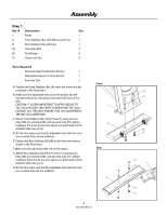
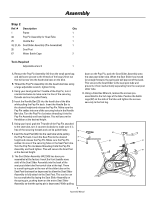
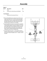
Assembly Step 1 Ref. # Description Qty 1 Frame 1 A Front Stabilizer Bar with Wheels and Feet 1 B Rear Stabilizer Bar with Feet 1 39 13mm Hex Bolt 4 50 Flat Washer 8 51 13mm Lock Nut 4 Tools Required Stamped Steel Combination Wrench 1 Adjustable wrench or 13mm Socket 1 5mm Hex Tool 1 A. Position the Front Stabilizer Bar (A) under the frame bracket as shown in the illustration. B. Make sure the adjustable feet are on the bottom and the transport wheels are facing up and toward the front of the bike. CAUTION: IT IS VERY IMPORTANT TO APPLY GREASE TO THE 13mm HEX BOLT (39) PRIOR TO MOUNTING THE 13mm LOCKNUT (51). THIS WILL ENSURE THAT YOU CAN REMOVE THE NUT AT A LATER DATE. C. Attach Front Stabilizer Bar (A) to Frame (1) using two hex bolts (39), four washers (50), and two lock nuts (51). Tighten hardware firmly but do not over tighten as deformation of the stabilizer tube may occur. D. At this time make sure that the adjustable feet with lock nuts are screwed fully into the stabilizer. E. Position the Rear Stabilizer Bar (B) on the frame bracket as shown in the illustration. F. Make sure the adjustable feet are on the bottom. G. Attach Rear Stabilizer Bar (B) to Frame (1) using two hex bolts (39), four washers (50), and two lock nuts (51). Tighten hardware firmly but do not over tighten as deformation of the stabilizer tube may occur. H. At this time make sure that the adjustable feet with lock nuts are screwed fully into the stabilizer. Front 1 A Rear B 6 Assembly Manual 39 50 50 51 39 1 50 50 51
-
 1
1 -
 2
2 -
 3
3 -
 4
4 -
 5
5 -
 6
6 -
 7
7 -
 8
8 -
 9
9 -
 10
10 -
 11
11 -
 12
12
 |
 |
