Seagate 15K.3 ST373453FC Model Product Manual PDF - Page 45
Installation - cheetah hard drive
 |
UPC - 000004165019
View all Seagate 15K.3 manuals
Add to My Manuals
Save this manual to your list of manuals |
Page 45 highlights
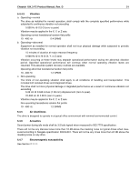
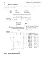
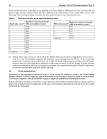
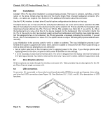
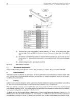
Cheetah 15K.3 FC Product Manual, Rev. D 35 8.0 Installation Cheetah 15K.3 FC disc drive installation is a plug-and-play process. There are no jumpers, switches, or terminators on the drive. Simply plug the drive into the host's 40-pin Fibre Channel backpanel connector (FC- SCA)-no cables are required. See Section 9.5 for additional information about this connector. Use the FC-AL interface to select drive ID and all option configurations for devices on the loop. If multiple devices are on the same FC-AL and physical addresses are used, set the device selection IDs (SEL IDs) on the backpanel so that no two devices have the same selection ID. This is called the hard assigned arbitrated loop physical address (AL_PA). There are 125 AL_PAs available (see Table 24). If you set the AL_PA on the backpanel to any value other than 0, the device plugged into the backpanel's SCA connector inherits this AL_PA. In the event you don't successfully assign unique hard addresses (and therefore have duplicate selection IDs assigned to two or more devices), the FC-AL generates a message indicating this condition. If you set the AL_PA on the backpanel to a value of 0, the system issues a unique soft-assigned physical address automatically. Loop initialization is the process used to verify or obtain an address. The loop initialization process is performed when power is applied to the drive, when a device is added or removed from the Fibre Channel loop, or when a device times out attempting to win arbitration. • Set all option selections in the connector prior to applying power to the drive. If you change options after applying power to the drive, recycle the drive power to activate the new settings. • It is not necessary to low-level format this drive. The drive is shipped from the factory low-level formatted in 512-byte logical blocks. You need to reformat the drive only if you want to select a different logical block size. 8.1 Drive ID/option selection All drive options are made through the interface connector (J1). Table provides the pin descriptions for the 40pin Fibre Channel single connector (J1). 8.2 LED connections A connector, J6, is provided on the printed circuit board assembly (PCBA) to provide port bypass, drive active, and drive fault LED connections (see Figure 15). See Sections 9.5.7, 9.5.8, and 9.5.9 for descriptions of LED functions. J6 Figure 14. Physical interface
-
 1
1 -
2
-
3
-
4
-
5
-
6
-
7
-
8
-
9
-
10
-
11
-
12
-
13
-
14
-
15
-
16
-
17
-
18
-
19
-
20
-
21
-
22
-
23
-
24
-
25
-
26
-
27
-
28
-
29
-
30
-
31
-
32
-
33
-
34
-
35
-
36
-
37
-
38
-
39
-
 40
40 -
 41
41 -
 42
42 -
 43
43 -
 44
44 -
 45
45 -
 46
46 -
 47
47 -
 48
48 -
 49
49 -
 50
50 -
51
-
52
-
53
-
54
-
55
-
56
-
57
-
58
-
59
-
60
-
61
-
62
-
63
-
64
-
65
-
66
-
67
-
68
-
69
-
70
-
71
-
72
-
73
-
74
-
75
-
76
-
77
-
78
-
79
-
80
-
81
-
82
-
83
-
84
-
85
-
86
 |
 |