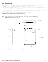
Seagate ST200FP0021 Seagate 600 Pro SSD Product Manual - Page 27
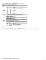
Table 10, 8 SATA Connector Plug Pinout
 |
View all Seagate ST200FP0021 manuals
Add to My Manuals
Save this manual to your list of manuals |
Page 27 highlights
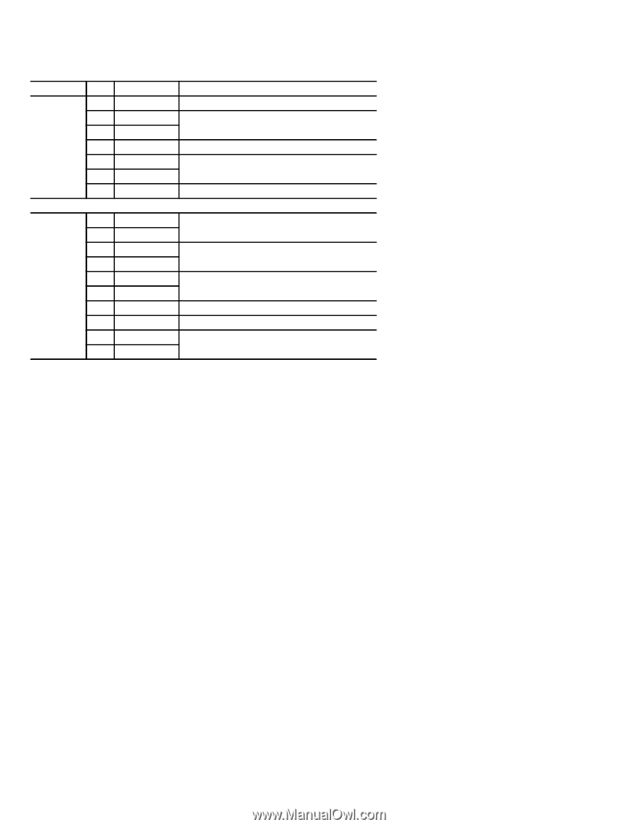
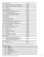
Table 10 summarizes the 1.8" drive Signal and Power SATA Plug. Table 10 1.8" SATA Connector Plug Pinout Segment Signal Power Pin Function Definition S1 GND Ground S2 A+ Differential Signal Pair (Host to Drive) S3 A- S4 GND Ground S5 B- Differential Signal Pair (Drive to Host) S6 B+ S7 GND Ground Spacing separates signal and power segments P1 V33 Unused [2] P2 V33 P3 GND Ground [1] P4 GND P5 V5 5V power to Drive P6 V5 P7 LED Signal Activity LED: Driven low to light Key Key Keyway P8 Optional Reserved for Seagate use. P9 Optional Leave unconnected. Notes: [1] Ground pins 3 and 4 mate first on micro SATA backplane connectors [2] The two V33 pins are unused but connected together on the drive. They can be used for a drive-in-place detection. SEAGATE 600 PRO SSD PRODUCT MANUAL, REV. B 23
-
 1
1 -
2
-
3
-
4
-
5
-
6
-
7
-
8
-
9
-
10
-
11
-
12
-
13
-
14
-
15
-
16
-
17
-
18
-
19
-
20
-
21
-
 22
22 -
 23
23 -
 24
24 -
 25
25 -
 26
26 -
 27
27 -
 28
28 -
 29
29 -
 30
30 -
 31
31 -
 32
32 -
33
-
34
-
35
-
36
-
37
-
38
-
39
-
40
-
41
 |
 |