Seagate ST300MP0014 Savvio 15K.1 SAS Product Manual - Page 69
Minimum OOB ALIGN burst amplitude
 |
View all Seagate ST300MP0014 manuals
Add to My Manuals
Save this manual to your list of manuals |
Page 69 highlights
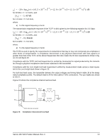
Table 17: Transmitter signal characteristics Signal characteristica Units 1.5 Gbps 3.0 Gbps a All tests in this table shall be performed with zero-length test load shown in figure 20. b The skew measurement shall be made at the midpoint of the transition with a repeating 0101b pattern on the physical link. The same stable trigger, coherent to the data stream, shall be used for both the Tx+ and Tx- signals. Skew is defined as the time difference between the means of the midpoint crossing times of the Tx+ signal and the Tx- signal. c The transmitter off voltage is the maximum A.C. voltage measured at compliance points when the transmitter is unpowered or transmitting D.C. idle (e.g., during idle time of an OOB signal). d Rise/fall times are measured from 20 % to 80 % of the transition with a repeating 0101b pattern on the physical link. e The maximum difference between the V+ and V- A.C. RMS transmitter amplitudes measured on a CJTPAT test pattern (see 9.5.2.3.3) into the test load shown in figure 20, as a percentage of the average of the V+ and V- A.C. RMS amplitudes. f The maximum difference in the average differential voltage (D.C. offset) component between the burst times and the idle times of an OOB signal. g The maximum difference in the average of the common mode voltage between the burst times and the idle times of an OOB signal. 9.5.2.3 Receiver signal characteristics Table 18 defines the compliance point requirements of the signal at the receiver end of a TxRx connection as measured into the test loads specified in figure 19 and figure 20. Table 18: Receiver signal characteristics Signal characteristic Jitter (see figure 16)b Units N/A 1.5 Gbps 3.0 Gbps See table 19 See table 19 2 x Z2 mV(P-P) 1,200 1,600 2 x Z1 X1a mV(P-P) UI 325 0.275 275 0.275 X2 Skewd UI 0.50 0.50 ps 80 75 Max voltage (non-op) Minimum OOB ALIGN burst amplitudec Maximum noise during OOB idle timec Max near-end crosstalke mV(P-P) mV(P-P) mV(P-P) mV(P-P) 2.000 240 120 100 2.000 240 120 100 a The value for X1 shall be half the value given for total jitter in table 19. The test or analysis shall include the effects of a single pole high-pass frequency-weighting function that progressively attenuates jitter at 20 dB/decade below a frequency of ((bit rate) / 1,667). b The value for X1 applies at a total jitter probability of 10-12. At this level of probability direct visual comparison between the mask and actual signals is not a valid method for determining compliance with the jitter output requirements. c With a measurement bandwidth of 1.5 times the baud rate (i.e. 4.5 GHz for 3.0 Gbps). d The skew measurement shall be made at the midpoint of the transition with a repeating 0101b pattern on the physical link. The same stable trigger, coherent to the data stream, shall be used for both the Rx+ and Rx- signals. Skew is defined as the time difference between the means of the midpoint crossing times of the Rx+ signal and the Rx- signal. e Near-end crosstalk is the unwanted signal amplitude at receiver terminals DR, CR, and XR coupled from signals and noise sources other than the desired signal. Refer to SFF-8410. Savvio 15K SAS Product Manual, Rev. C 63
-
 1
1 -
2
-
3
-
4
-
5
-
6
-
7
-
8
-
9
-
10
-
11
-
12
-
13
-
14
-
15
-
16
-
17
-
18
-
19
-
20
-
21
-
22
-
23
-
24
-
25
-
26
-
27
-
28
-
29
-
30
-
31
-
32
-
33
-
34
-
35
-
36
-
37
-
38
-
39
-
40
-
41
-
42
-
43
-
44
-
45
-
46
-
47
-
48
-
49
-
50
-
51
-
52
-
53
-
54
-
55
-
56
-
57
-
58
-
59
-
60
-
61
-
62
-
63
-
 64
64 -
 65
65 -
 66
66 -
 67
67 -
 68
68 -
 69
69 -
 70
70 -
 71
71 -
 72
72 -
 73
73 -
 74
74 -
75
-
76
-
77
-
78
-
79
-
80
-
81
-
82
-
83
-
84
 |
 |
