Seagate ST32000646SS Constellation ES.1 SAS Product Manual - Page 79
SAS-2 Specification Compliance, Additional information
 |
View all Seagate ST32000646SS manuals
Add to My Manuals
Save this manual to your list of manuals |
Page 79 highlights
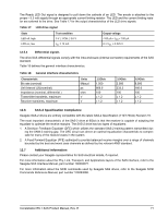
The Ready LED Out signal is designed to pull down the cathode of an LED. The anode is attached to the proper +3.3 volt supply through an appropriate current limiting resistor. The LED and the current limiting resistor are external to the drive. See Table 17 for the output characteristics of the LED drive signals. Table 17: LED drive signal State LED off, high LED on, low Test condition 0 V ≤ VOH ≤ 3.6 V IOL = 15 mA Output voltage -100 μA < IOH < 100 μA 0 ≤ VOL ≤ 0.225 V 12.5.2 Differential signals The drive SAS differential signals comply with the intra-enclosure (internal connector) requirements of the SAS standard. Table 18 defines the general interface characteristics. Table 18: General interface characteristics Characteristic Bit rate (nominal) Unit interval (UI)(nominal) Impedance (nominal, differential ) Transmitter transients, maximum Receiver transients, maximum Units Mbaud ps ohm V V 1.5Gb/s 1,500 666.6 100 ± 1.2 ± 1.2 3.0Gb/s 3,000 333.3 100 ± 1.2 ± 1.2 6.0Gb/s 6,000 166.6 100 ± 1.2 ± 1.2 12.6 SAS-2 Specification Compliance Seagate SAS-2 drives are entirely compatible with the latest SAS-2 Specification (T10/1760-D) Revision 16. The most important characteristic of the SAS-2 drive at 6Gb/s is that the receiver is capable of adapting the equalizer to optimize the receive margins. The SAS-2 drive has two types of equalizers: 1. A Decision Feedback Equalizer (DFE) which utilizes the standard SAS-2 training pattern transmitted during the SNW-3 training gap. The DFE circuit can derive an optimal equalization characteristic to compensate for many of the receive losses in the system. 2. A Feed Forward Equalizer (FFE) optimized to provide balanced receive margins over a range of channels bounded by the best and worst case channels as defined by the relevant ANSI standard. 12.7 Additional information Please contact your Seagate representative for SAS electrical details, if required. For more information about the Phy, Link, Transport, and Applications layers of the SAS interface, refer to the Seagate SAS Interface Manual, part number 100293071. For more information about the SCSI commands used by Seagate SAS drives, refer to the Seagate SCSI Commands Reference Manual, part number 100293068. Constellation ES.1 SAS Product Manual, Rev. E 71
-
 1
1 -
2
-
3
-
4
-
5
-
6
-
7
-
8
-
9
-
10
-
11
-
12
-
13
-
14
-
15
-
16
-
17
-
18
-
19
-
20
-
21
-
22
-
23
-
24
-
25
-
26
-
27
-
28
-
29
-
30
-
31
-
32
-
33
-
34
-
35
-
36
-
37
-
38
-
39
-
40
-
41
-
42
-
43
-
44
-
45
-
46
-
47
-
48
-
49
-
50
-
51
-
52
-
53
-
54
-
55
-
56
-
57
-
58
-
59
-
60
-
61
-
62
-
63
-
64
-
65
-
66
-
67
-
68
-
69
-
70
-
71
-
72
-
73
-
 74
74 -
 75
75 -
 76
76 -
 77
77 -
 78
78 -
 79
79 -
 80
80 -
 81
81 -
 82
82 -
 83
83 -
 84
84 -
85
-
86
-
87
-
88
 |
 |
