Seagate ST3300655LC Cheetah 15K.5 SAS Product Manual - Page 31
The +12V and +5V current profiles for ST3146854SS, ST373454SS and ST336754SS models are shown
 |
View all Seagate ST3300655LC manuals
Add to My Manuals
Save this manual to your list of manuals |
Page 31 highlights
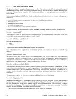
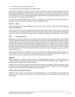
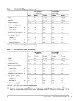
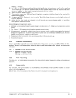
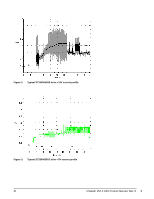
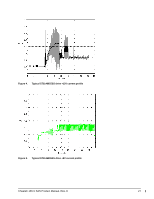
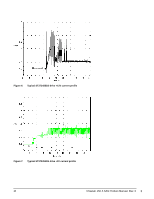
Degrees C ambient. [2] For +12 V, a -10% tolerance is allowed during initial spindle start but must return to ±5% before reaching 15,000 RPM. The ±5% must be maintained after the drive signifies that its power-up sequence has been completed and that the drive is able to accept selection by the host initiator. [3] See +12V current profile in Figure 2. [4] This condition occurs after OOB and Speed Negotiation completes but before the drive has received the Notify Spinup primitive. [5] See paragraph 6.2.1, "Conducted noise immunity." Specified voltage tolerance includes ripple, noise, and transient response. [6] During idle, the drive heads are relocated every 60 seconds to a random location within the band from three-quarters to maximum track. General DC power requirement notes. 1. Minimum current loading for each supply voltage is not less than 1.7% of the maximum operating current shown. 2. The +5V and +12V supplies should employ separate ground returns. 3. Where power is provided to multiple drives from a common supply, careful consideration for individual drive power requirements should be noted. Where multiple units are powered on simultaneously, the peak starting current must be available to each device. 4. Parameters, other than spindle start, are measured after a 10-minute warm up. 5. No terminator power. 6.2.1 Conducted noise immunity Noise is specified as a periodic and random distribution of frequencies covering a band from DC to 10 MHz. Maximum allowed noise values given below are peak-to-peak measurements and apply at the drive power connector. +5V = 250 mV pp from 0 to 100 kHz to 20 MHz. +12V = 800 mV pp from 100 Hz to 8 KHz. 450 mV pp from 8 KHz to 20 KHz. 250 mV pp from 20 KHz to 5 MHz. 6.2.2 Power sequencing The drive does not require power sequencing. The drive protects against inadvertent writing during power-up and down. 6.2.3 Current profiles The +12V and +5V current profiles for ST3146854SS, ST373454SS and ST336754SS models are shown below in the following figures. Note: All times and currents are typical. See Tables 2, 3, and 4 for maximum current requirements. Cheetah 15K.5 SAS Product Manual, Rev. E 25
-
 1
1 -
2
-
3
-
4
-
5
-
6
-
7
-
8
-
9
-
10
-
11
-
12
-
13
-
14
-
15
-
16
-
17
-
18
-
19
-
20
-
21
-
22
-
23
-
24
-
25
-
 26
26 -
 27
27 -
 28
28 -
 29
29 -
 30
30 -
 31
31 -
 32
32 -
 33
33 -
 34
34 -
 35
35 -
 36
36 -
37
-
38
-
39
-
40
-
41
-
42
-
43
-
44
-
45
-
46
-
47
-
48
-
49
-
50
-
51
-
52
-
53
-
54
-
55
-
56
-
57
-
58
-
59
-
60
-
61
-
62
-
63
-
64
-
65
-
66
-
67
-
68
-
69
-
70
-
71
-
72
-
73
-
74
-
75
-
76
-
77
-
78
-
79
-
80
-
81
-
82
-
83
-
84
-
85
-
86
 |
 |