Seagate ST450MP0074 Savvio 15K SAS Product Manual - Page 74
Electrical TxRx connections, 5.2.4.1, Transmitter characteristics, Table 21, Impedance
 |
View all Seagate ST450MP0074 manuals
Add to My Manuals
Save this manual to your list of manuals |
Page 74 highlights
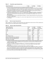
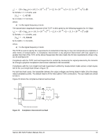
Table 21: Impedance requirements (Sheet 2 of 2) Requirement Units 1.5 Gbps 3.0 Gbps a All times indicated for time domain reflectometer measurements are recorded times. Recorded times are twice the transit time of the time domain reflectometer signal. b All measurements are made through mated connector pairs. c The media impedance measurement identifies the impedance mismatches present in the media when terminated in its characteristic impedance. This measurement excludes mated connectors at both ends of the media, when present, but includes any intermediate connectors or splices. The mated connectors measurement applies only to the mated connector pair at each end, as applicable. d Where the media has an electrical length of > 4 ns the procedure detailed in SFF-8410, or an equivalent procedure, shall be used to determine the impedance. e The receiver termination impedance specification applies to all receivers in a TxRx connection and covers all time points between the connector nearest the receiver, the receiver, and the transmission line terminator. This measurement shall be made from that connector. f At the time point corresponding to the connection of the receiver to the transmission line the input capacitance of the receiver and its connection to the transmission line may cause the measured impedance to fall below the minimum impedances specified in this table. The area of the impedance dip (amplitude as ρ, the reflection coefficient, and duration in time) caused by this capacitance is the receiver termination time constant. The receiver time constant shall not be greater than the values shown in this table. An approximate value for the receiver termination time constant is given by the product of the amplitude of the dip (as ρ) and its width (in ps) measured at the half amplitude point. The amplitude is defined as being the difference in the reflection coefficient between the reflection coefficient at the nominal impedance and the reflection coefficient at the minimum impedance point. The value of the receiver excess input capacitance is given by the following equation: C = r--e----c---e---i-v---e----r---t--e---r--m-----i--n---a---t--i--o---n-----t--i-m-----e-----c---o---n----s--t--a----n---t (R0 | RR) where (R0 || RR) is the parallel combination of the transmission line characteristic impedance and termination resistance at the receiver. g The difference in measured impedance to ground on the plus and minus terminals on the interconnect, transmitter or receiver, with a differential test signal applied to those terminals. 9.5.2.4 Electrical TxRx connections TxRx connections may be divided into TxRx connection segments. In a single TxRx connection individual TxRx connection segments may be formed from differing media and materials, including traces on printed wiring boards and optical fibers. This subclause applies only to TxRx connection segments that are formed from electrically conductive media. Each electrical TxRx connection segment shall comply with the impedance requirements of table 21 for the media from which they are formed. An equalizer network, if present, shall be part of the TxRx connection. TxRx connections that are composed entirely of electrically conducting media shall be applied only to homogenous ground applications (e.g., between devices within an enclosure or rack, or between enclosures interconnected by a common ground return or ground plane). 9.5.2.4.1 Transmitter characteristics The drive are D.C. coupled. A combination of a zero-length test load and the transmitter compliance transfer function (TCTF) test load methodology is used for the specification of transmitter characteristics. This methodology specifies the transmitter signal at the test points on the required test loads. The transmitter uses the same settings (e.g., preemphasis, voltage swing) with both the zero-length test load and the TCTF test load. The signal specifications at IR are met under each of these loading conditions. The TCTF is the mathematical statement of the transfer function through which the transmitter shall be capable of producing acceptable signals as defined by a receive mask. The transmission magnitude response of the TCTF in dB is given by the following equation for 1.5 Gbps: 66 Savvio 15K SAS Product Manual, Rev. B
-
 1
1 -
2
-
3
-
4
-
5
-
6
-
7
-
8
-
9
-
10
-
11
-
12
-
13
-
14
-
15
-
16
-
17
-
18
-
19
-
20
-
21
-
22
-
23
-
24
-
25
-
26
-
27
-
28
-
29
-
30
-
31
-
32
-
33
-
34
-
35
-
36
-
37
-
38
-
39
-
40
-
41
-
42
-
43
-
44
-
45
-
46
-
47
-
48
-
49
-
50
-
51
-
52
-
53
-
54
-
55
-
56
-
57
-
58
-
59
-
60
-
61
-
62
-
63
-
64
-
65
-
66
-
67
-
68
-
 69
69 -
 70
70 -
 71
71 -
 72
72 -
 73
73 -
 74
74 -
 75
75 -
 76
76 -
 77
77 -
 78
78 -
 79
79 -
80
-
81
-
82
-
83
-
84
-
85
-
86
 |
 |