Seagate ST960821A Momentus 4200.2 PATA Product Manual - Page 24
Drive mounting
 |
View all Seagate ST960821A manuals
Add to My Manuals
Save this manual to your list of manuals |
Page 24 highlights
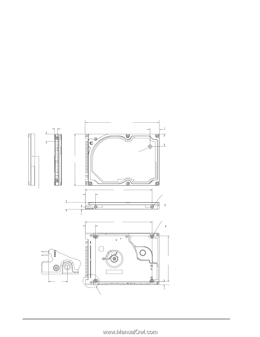
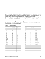
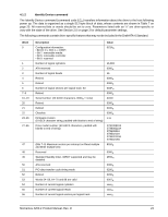
3.2.2 Cable-select option Computers that use cable select determine the master and slave drives by selecting or deselecting pin 28, CSEL, on the interface bus. Master and slave drives are determined by their physical position on the cable. To enable cable select, set a jumper as shown in Figure 3. Refer to your computer manual to determine whether your computer supports this option. 3.3 Drive mounting You can mount the drive using four screws in the side-mounting holes or four screws in the bottom-mounting holes. See Figure 4 for drive mounting dimensions (dimensions in inches with mm in parentheses). Follow these important mounting precautions when mounting the drive: • Allow a minimum clearance of 0.030 inches (0.76 mm) around the entire perimeter of the drive for cooling. • Use only M3 x 0.5 mounting screws. • Do not overtighten the mounting screws (maximum torque: 4.0 inch-lb). • Four (4) threads (0.080 inches) minimum screw engagement recommended. .399 (10.135) .157 (3.9878) 2.750 +/- .010 (69.85 +/- .25) 3.945 +/-0.010 (100.2 +/-.25) Breather Hole Do not cover or seal. 0.490 +/- .010 (12.446 +/- .254) 0.673 +/- .010 (17.09 +/- .254) Recommended case temp. measurement location .374 +/- .008 (9.5 +/- .2) 2X .118 (3.00) Both sides .551 (13.99) inches (mm) .551 (13.99) 3.567 (90.60) 3.567 (90.60) .399 (10.135) Detail A Detail A Figure 4. Mounting dimensions-top, side and end view 18 2X M3 X 0.5-6H Mounting holes Both sides .12 min. full thread 4X M3 X 0.5-6H Mounting holes .10 min. full thread 2.430 (61.72) .160 (4.06) Momentus 4200.2 Product Manual, Rev. D
-
 1
1 -
2
-
3
-
4
-
5
-
6
-
7
-
8
-
9
-
10
-
11
-
12
-
13
-
14
-
15
-
16
-
17
-
18
-
 19
19 -
 20
20 -
 21
21 -
 22
22 -
 23
23 -
 24
24 -
 25
25 -
 26
26 -
 27
27 -
 28
28 -
 29
29 -
30
-
31
-
32
-
33
-
34
-
35
-
36
-
37
-
38
-
39
-
40
-
41
-
42
-
43
-
44
 |
 |