Seagate SV35 Series SV35 Series SATA Product Manual - Page 35
There are three power pins for each voltage. One pin from each voltage is used for pre-charge when
 |
View all Seagate SV35 Series manuals
Add to My Manuals
Save this manual to your list of manuals |
Page 35 highlights
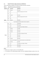
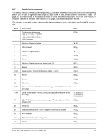
case, the mating sequences are: • the ground pins P4 and P12. • the pre-charge power pins and the other ground pins. • the signal pins and the rest of the power pins. 3. There are three power pins for each voltage. One pin from each voltage is used for pre-charge when installed in a blind-mate backplane configuration. 4. All used voltage pins (Vx) must be terminated. SV35 Series SATA Product Manual, Rev. B 29
-
 1
1 -
2
-
3
-
4
-
5
-
6
-
7
-
8
-
9
-
10
-
11
-
12
-
13
-
14
-
15
-
16
-
17
-
18
-
19
-
20
-
21
-
22
-
23
-
24
-
25
-
26
-
27
-
28
-
29
-
 30
30 -
 31
31 -
 32
32 -
 33
33 -
 34
34 -
 35
35 -
 36
36 -
 37
37 -
 38
38 -
 39
39 -
 40
40 -
41
-
42
-
43
-
44
-
45
-
46
-
47
-
48
-
49
-
50
-
51
-
52
-
53
-
54
-
55
-
56
-
57
-
58
-
59
-
60
-
61
-
62
 |
 |

SV35 Series SATA Product Manual, Rev. B
29
case, the mating sequences are:
•
the ground pins P4 and P12.
•
the pre-charge power pins and the other ground pins.
•
the signal pins and the rest of the power pins.
3.
There are three power pins for each voltage. One pin from each voltage is used for pre-charge when
installed in a blind-mate backplane configuration.
4.
All used voltage pins (V
x
) must be terminated.