Seiko V657 Parts Catalog - Page 3
Technical, Guide
 |
View all Seiko V657 manuals
Add to My Manuals
Save this manual to your list of manuals |
Page 3 highlights
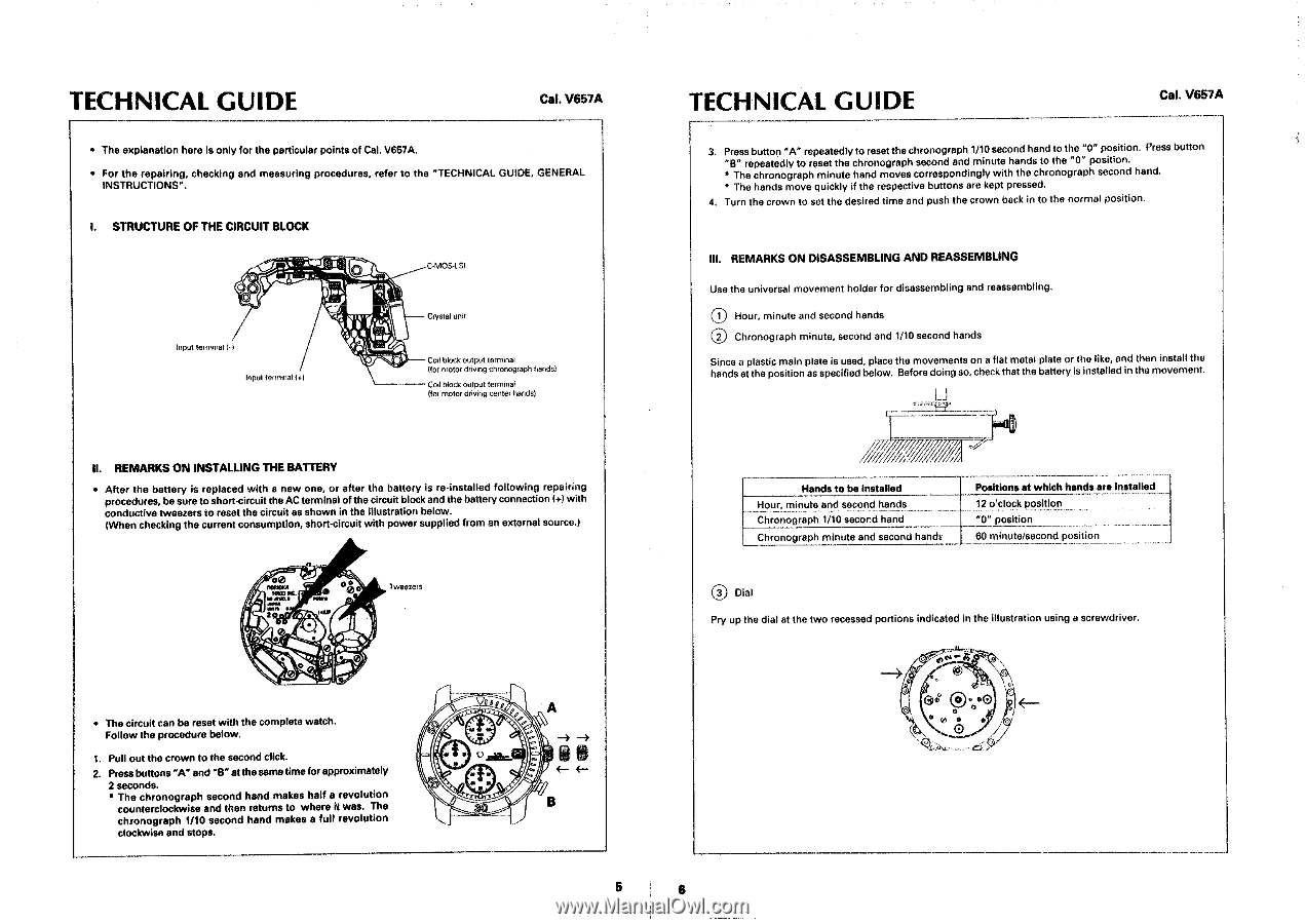
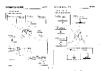
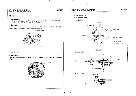
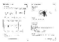
TECHNICAL GUIDE Cal. VS57A • The explanation here is only for the particular points of Cal, V657A. • For the repairing, checking and measuring procedures, refer to the "TECHNICAL GUIDE, GENERAL INSTRUCTIONS", I. STRUCTURE OF THE CIRCUIT BLOCK 0 Input tot minat Input terminal 1+) O C-MOS-LSI Crystal unit -- Coil block output terminal (for motor driving chronograph hands) -- Cod block output terminal (tor motor driving center handsl II. REMARKS ON INSTALLING THE BATTERY • After the battery is replaced with a new one, or after the battery is re-installed following repairing procedures, be sure to short-circuit the AC terminal of the circuit block and the battery connection I+) with conductive tweezers to reset the circuit as shown in the illustration below. (When checking the current consumption, short-circuit with power supplied from an external source.) 0® ti0NIPICA MEI W. AVM -'I MOSI1 • 20 - fi PIAM• NO/ 000 0 • 0 0 • ,to tweezers • The circuit can be reset with the complete watch. Follow the procedure below. 1. Pull out the crown to the second click. 2. Press buttons "A" and "B" at the sometime for approximately 2 seconds. * The chronograph second hand makes half a revolution counterclockwise and then returns to where it was. The chronograph 1/10 second hand makes a full revolution clockwise and stops. 4.4 A Id all B 5 TECHNICAL GUIDE Cal. V657A 3. Press button "A" repeatedly to reset the chronograph 1/10 second hand to the "0" position. Press button "B" repeatedly to reset the chronograph second and minute hands to the "0" position. * The chronograph minute hand moves correspondingly with the chronograph second hand. * The hands move quickly if the respective buttons are kept pressed. 4, Turn the crown to set the desired time and push the crown back in to the normal position. III. REMARKS ON DISASSEMBLING AND REASSEMBLING Use the universal movement holder for disassembling and reassembling. 0 -) Hour, minute and second hands 0 Chronograph minute, second and 1/10 second hands Since a plastic main plate is used, place the movements on a flat metal plate or the like, and then install the hands at the position as specified below. Before doing so, chock that the battery is installed in the movement. Li f-4 r. Hands to be installed Hour, minute and second hands Chronograph 1/10 secor.d hand Chronograph minute and second hands Positions M which hands are installed 12 o'clock position "0" position 60 minute/second position (D Dial Pry up the dial at the two recessed portions indicated in the illustration using a screwdriver. (I cio? •C) O 0 e •
-
 1
1 -
 2
2 -
 3
3 -
 4
4 -
 5
5 -
 6
6
 |
 |