Sennheiser EW 100 G4-865 Instruction manual ew 100 G4 PDF - Page 55
Slide the antenna splitter with the mounted blanking plate into the 19
 |
View all Sennheiser EW 100 G4-865 manuals
Add to My Manuals
Save this manual to your list of manuals |
Page 55 highlights
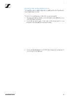
Installing the ASA 214 ▷ Attach the antennas. You have the following options: • Connect the supplied rod antennas on the rear side of the antenna splitter. In this case, cover the antenna holes with the two covers (left diagram). • Attach the AM 2 antenna front mounting set (optional accessory) and mount the rod antennas on the blanking plate (right diagram). ► ► ▷ Slide the antenna splitter with the mounted blanking plate into the 19" rack. ▷ Secure the mounting angle and the blanking plate to the 19" rack. ▷ Align the mounted antennas in a V-shape. 54
-
 1
1 -
2
-
3
-
4
-
5
-
6
-
7
-
8
-
9
-
10
-
11
-
12
-
13
-
14
-
15
-
16
-
17
-
18
-
19
-
20
-
21
-
22
-
23
-
24
-
25
-
26
-
27
-
28
-
29
-
30
-
31
-
32
-
33
-
34
-
35
-
36
-
37
-
38
-
39
-
40
-
41
-
42
-
43
-
44
-
45
-
46
-
47
-
48
-
49
-
 50
50 -
 51
51 -
 52
52 -
 53
53 -
 54
54 -
 55
55 -
 56
56 -
 57
57 -
 58
58 -
 59
59 -
 60
60 -
61
-
62
-
63
-
64
-
65
-
66
-
67
-
68
-
69
-
70
-
71
-
72
-
73
-
74
-
75
-
76
-
77
-
78
-
79
-
80
-
81
-
82
-
83
-
84
-
85
-
86
-
87
-
88
-
89
-
90
-
91
-
92
-
93
-
94
-
95
-
96
-
97
-
98
-
99
-
100
-
101
-
102
-
103
-
104
-
105
-
106
-
107
-
108
-
109
-
110
-
111
-
112
-
113
-
114
-
115
-
116
-
117
-
118
-
119
-
120
-
121
-
122
-
123
-
124
-
125
-
126
-
127
-
128
-
129
-
130
-
131
-
132
-
133
-
134
-
135
-
136
-
137
-
138
-
139
-
140
-
141
-
142
-
143
-
144
 |
 |

Installing the ASA 214
54
▷
Attach the antennas. You have the following options:
• Connect the supplied rod antennas on the rear side of the antenna
splitter. In this case, cover the antenna holes with the two covers (left
diagram).
•
Attach the
AM 2
antenna front mounting set (optional accessory) and
mount the rod antennas on the blanking plate (right diagram).
►
►
▷
Slide the antenna splitter with the mounted blanking plate into the 19"
rack.
▷
Secure the mounting angle and the blanking plate to the 19" rack.
▷
Align the mounted antennas in a V-shape.