Sharp 19C140 Service Manual
Sharp 19C140 - 19" CRT TV Manual
 |
UPC - 074000360259
View all Sharp 19C140 manuals
Add to My Manuals
Save this manual to your list of manuals |
Sharp 19C140 manual content summary:
- Sharp 19C140 | Service Manual - Page 1
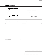
19C140 SERVICE MANUAL COLOR TELEVISION Chassis No. CD-A MODELS 19C140 IMPORTANT SERVICE SAFETY PRECAUTION 2 » LOCATION OF USER'S CONTROL ...4 » INSTALLATION AND SERVICE INSTRUCTIONS prior notice. SHARP CORPORATION This document has been published to be used for after sales service only. The - Sharp 19C140 | Service Manual - Page 2
service personnel are aware of the procedures and instructions covering X-radiation. The only potential source of X-ray in current solid state TV an X-radiation problem. Every time a color chassis is serviced, the brightness voltage circuitry. 6. When troubleshooting and taking test measurements on - Sharp 19C140 | Service Manual - Page 3
19C140 IMPORTANT SERVICE SAFETY PRECAUTION (Continued) BEFORE RETURNING THE RECEIVER (Fire & Shock television factory recommended necessarily increased by using replacement components replacement parts shown in this service manual, may rated for higher voltage, wattage and etc. create shock, - Sharp 19C140 | Service Manual - Page 4
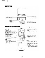
19C140 LOCATION OF USER'S CONTROL 4 - Sharp 19C140 | Service Manual - Page 5
19C140 INSTALLATION AND SERVICE INSTRUCTIONS Note: (1) When performing any adjustments to resistor controls and transformers use non-metallic screwdrivers or TV alignment tools. (2) Before performing adjustments, the TV set must be on at least 15 minutes. CIRCUIT PROTECTION HIGH VOLTAGE CHECK - Sharp 19C140 | Service Manual - Page 6
up and Ch-up buttons at the sametime, plug the AC cord into a wall socket. Now the TV set is switched on and enters the service mode. To exit the service mode, turn the television off by pressing the power button. DATA NUMBER SERVICE ADJUSTMENT NUMBER CHANNEL S01 55(085) 02 S01 D:00 Figure A. 6 - Sharp 19C140 | Service Manual - Page 7
19C140 SERVICE NUMBER ADJUSTMENT ITEM S01 PICTURE S02 TINT S03 COLOR S04 BRIGHTNESS S05 SHARPNESS S06 VERTICAL PHASE S07 " Table - A Holding down both the CH-up/down buttons on the TV set at service mode for more than 2 seconds will automatically write the above initial values into - Sharp 19C140 | Service Manual - Page 8
19C140 Ë SERVICE ADJUSTMENT VCO Adjustment 1. Connect a digital voltmeter between pin (44) of IC201 and ground. 2. Receive a good local channel. 3. Enter the service mode and select the service adjustment "S10". 4. Adjust the data so that digital voltmeter reads 2.2V. 5. Adjustment is completed, - Sharp 19C140 | Service Manual - Page 9
19C140 DESCRIPTION OF SCHEMATIC DIAGRAM NOTES: 1. The unit of resistance "ohm" is omitted. (K=kΩ=1000Ω, M=MΩ) 2. All resistors are 1/10 watt, unless otherwise noted. 3. All capacitors are µF, unless - Sharp 19C140 | Service Manual - Page 10
19C140 CHASSIS LAYOUT H NORMAL G F E D PR701 C708 C B A 1 2 3 4 5 6 10 - Sharp 19C140 | Service Manual - Page 11
BLOCK DIAGRAM H 19C140 G F E D C B A 1 2 3 4 5 6 11 - Sharp 19C140 | Service Manual - Page 12
19C140 SCHEMATIC DIAGRAM: MAIN-1 Unit H G F E D C B A 1 2 3 4 5 6 7 8 9 10 12 - Sharp 19C140 | Service Manual - Page 13
19C140 10 11 12 13 14 15 16 17 18 19 13 - Sharp 19C140 | Service Manual - Page 14
19C140 SCHEMATIC DIAGRAM: CRT Unit H G F E D C B A 1 2 3 4 5 6 14 - Sharp 19C140 | Service Manual - Page 15
PRINTED WIRING BOARD ASSEMBLIES H 19C140 G F E D C B P WB -A: MAIN Unit (Wiring S ide) A 1 2 3 4 5 6 15 - Sharp 19C140 | Service Manual - Page 16
19C140 H \ \r \ G F E D C B \ \n \r \r \ \f \r \r \n \r \r \ \r \r \r \ \r \n \n \n \ \f \ \ \ \ \ \ \n \ \ \ \ \ \ \ \ \f \f \f \ \ \ \ \ \n \ \n \n \b \r \b \r\ \r\ \n \b \b \b \f \f \ \ \ \n \n \n \r \r \n\ \b \b \r \b \r \r \f \ \n \n \n \n \n \n \n \n \n \n - Sharp 19C140 | Service Manual - Page 17
19C140 H G F PWB-B: CRT Unit (Wiring Side) E D \b\ \b\ \b\ \b \b\ \b \b \b \b \b\ \b \b C \b\ \b \b B PWB-B: CRT Unit (Chip Parts Side) A 1 2 3 4 5 6 17 - Sharp 19C140 | Service Manual - Page 18
in this service manual may create shock, fire or other hazards. "HOW TO ORDER REPLACEMENT PARTS" To have your order filled promptly and correctly, please furnish the following informations. 1. MODEL NUMBER 3. PART NO. 2. REF. NO. 4. DESCRIPTION in USA: Contact your nearest SHARP - Sharp 19C140 | Service Manual - Page 19
19C140 Ref. No. Part No. « Description Code PWB-A: DUNTKA358WEX9 MAIN UNIT (Continued) CONTROL R738 RVR-M4588CEZZ+ X 22k 130V Adj. AB CAPACITORS [EL.··· Electrolytic, M-Poly.··· Metalized Polypro - Sharp 19C140 | Service Manual - Page 20
19C140 Ref. No. Part No. « Description Code PWB-A: DUNTKA358WEX9 MAIN UNIT R209 R210 R211 R212 R215 R220 R301 R302 R353 R354 R355 R357 R401 R402 R403 - Sharp 19C140 | Service Manual - Page 21
X FERRITE BEAD AB FB601 RBLN-0047CEZZY X FERRITE BEAD AB FB2002 RBLN-0037CEZZY X FERRITE BEAD AB JA409 RBLN-0047CEZZY X FERRITE BEAD AB 21 19C140 Ref. No. Part No. « Description Code JACK J903 J905 QJAKE0211CE09 X RCA JACK WHITE AB QJAKE0211CE04 X RCA JACK YELLOW AB Plug P302 - Sharp 19C140 | Service Manual - Page 22
19C140 Ref. No. AC CORD HOLDER AB LHLDZ0063PEZZ X HOLDER AB TLABM0002GJZZ X Model label mono voltge UL AB TLABN0101GJZZ X REMARK LABEL AB XTASD30P12000 SCREW (CAB) AA SUPPLIED ACCESORRIES TINS-B244WJZZ X OPERATION MANUAL - RRMCG1324CESC X R/C GUN AH TCAUS3000GJZZ X CAUTION LABEL AA - Sharp 19C140 | Service Manual - Page 23
5 Wrapping Paper PACKING OF THE SET 5 Polyethylene Bag 19C140 Operation Manual Infrared R/C Unit 5 Batteries 5 Buffer Material FRONT 5 MARK : Not replacement items. 23 5 Packing Case REAR Use tape to fix the top side of packing case. Use 10 staples to fix the bottom side of packing case. - Sharp 19C140 | Service Manual - Page 24
19C140 COPYRIGHT © 2004 BY SHARP CORPORATION ALL RIGHTS RESERVED. No part of this publication may Information Design base : JAPAN Production : SEMEX J B SHARP ELECTRONICA MEXICO S. A. DE C. V. Quality & Reliability Control Center Blvd. SHARP No. 3510 Parque Industrial Rosarito Playas de Rosarito,
-
 1
1 -
 2
2 -
 3
3 -
 4
4 -
 5
5 -
 6
6 -
 7
7 -
8
-
9
-
10
-
11
-
12
-
13
-
14
-
15
-
16
-
17
-
18
-
19
-
20
-
21
-
22
-
23
-
24
 |
 |
COLOR TELEVISION
Chassis No. CD-A
In the interests of user-safety (Required by safety regulations in some countries) the set should be restored to its
original condition and only parts identical to those specified should be used.
»
ELECTRICAL SPECIFICATIONS
.........................................................................................................
1
»
IMPORTANT SERVICE SAFETY PRECAUTION
.................................................................................
2
»
LOCATION OF USER'S CONTROL
.....................................................................................................
4
»
INSTALLATION AND SERVICE INSTRUCTIONS
................................................................................
5
»
CHASSIS LAYOUT
............................................................................................................................
10
»
BLOCK DIAGRAM
.............................................................................................................................
11
»
SCHEMATIC DIAGRAMS
..................................................................................................................
12
»
PRINTED WIRING BOARD ASSEMBLIES
........................................................................................
15
»
REPLACEMENT PARTS LIST
...........................................................................................................
18
»
PACKING OF THE SET
.....................................................................................................................
23
Page
SHARP CORPORATION
This document has been published to be used for after
sales service only.
The contents are subject to change without notice.
CONTENTS
SERVICE MANUAL
POWER INPUT
................................
120 V AC 60 Hz
POWER RATING
.............................................
69 W
PICTURE SIZE
.......................
1,194cm
2
(185sq inch)
CONVERGENCE
........................................
Magnetic
SWEEP DEFLECTION
................................
Magnetic
FOCUS
...........................
Hi-Bi-Potential Electrostatic
INTERMEDIATE FREQUENCIES
Picture IF Carrier Frequency
.................
45.75 MHz
Sound IF Carrier Frequency
..................
41.25 MHz
Color Sub-Carrier Frequency
................
42.17 MHz
(Nominal)
ELECTRICAL SPECIFICATIONS
AUDIO POWER
OUTPUT RATING
...........
1.0 W (at 10% distortion)
SPEAKER
SIZE
..................................................
8 cm (Round)
VOICE COIL IMPEDANCE
...........
8 ohm at 400 Hz
ANTENNA INPUT IMPEDANCE
VHF/UHF
................................
75 ohm Unbalanced
TUNING RANGES
VHF-Channels
..........................................
2 thru 13
UHF-Channels
........................................
14 thru 69
CATV Channels
......................................
1 thru 125
(EIA, Channel Plan U.S.A.)
Specifications are subject to change without
prior notice.
MODELS
19C140
19C140