Sharp 32F630 Service Manual - Page 10
Service Adjustment - parts
 |
UPC - 074000357419
View all Sharp 32F630 manuals
Add to My Manuals
Save this manual to your list of manuals |
Page 10 highlights
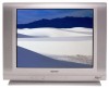
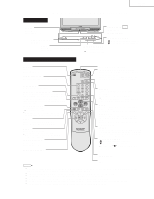
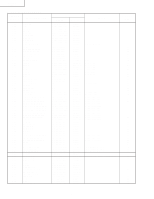
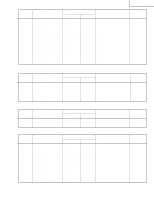
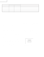
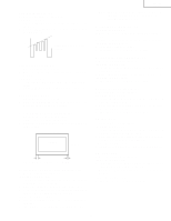
32F630 32F631 Holding down both the VOL-up and CH-up buttons on the TV set at service mode for more than 2 seconds will PART REPLACED IC2001 IC201 IC2101 CRT IC3001 ADJUSTMENT NECESSARY UNNECESSARY X X X X X NOTES Data is stored in IC2101. The adjustment is needed to compensate for characteristics of parts Holding down both the VOL-up and CH-up buttons on the TV set in the service mode for more than 2 seconds will automatically write the Adjust items related to picture tube only. Adjust items related to MTS only (M01~M20). SERVICE ADJUSTMENT RF AGC Adjustment 1. Receive a good local channel. 2. Enter the service mode and select the service adjustment "R01". 3. Set the data value to point where no noise or beat appears. 4. Select another channel to confirm that no noise or beat appears. Note 1 : You will have to come out of the service mode to select another channel. Note 2 : Setting the data to "00" will produce a black raster. Screen Adjustment 1. Receive a good local channel. 2. Enter the service mode and select the service adjustment "V03" and set the data value to "00" to set the color level to minimum. (Record original data code under adjustment "V03" before changing) You may skip this step, if you selected a B/W picture or monoscope pattern. 3. Select the service adjustment "V11" and adjust the data value to "01", this turn off the luminance signal (Y-mute). 4. Adjust the master screen control until the raster darkens to the point where raster is barely seen. 5. Adjust the service adjustments "V06" red, "V07" green and "V08" blue to obtain a good grey scale with normal whites at low brightness level. 6. Select the service adjustment "V11" and reset data to "00". Select the service adjustment "V03" and reset data to obtain normal color level. 7. For component input, the data value of "V46" red, "V47" green and "V48" blue is adjusted to follow the data value of "V06", "V07" and "V08" respectively. 8. Reset the master screen control to obtain normal brightness range. White Balance Adjustment 1. Receive a good local channel. 2. Enter the service mode and select the service adjustment "V03" and set to "00" (minimum color)(Record original data code under adjustment "V03" before changing). "V03" does not have to be adjusted, if you selected a B/W picture or monoscope pattern. 3. Alternately adjust the service adjustment data of "V09" and "V10" until a good grey scale with normal whites is obtained. (RF Input) 4. For component input, the data value of "V49" and "V50" is adjusted to follow the data value of "V09" and "V10" respectively. 5. Select the service adjustment "V03" and reset data to obtain normal color level. Sub-picture and Sub-Bright Adjustments 1. Receive the window pattern signal. • RF INPUT (TU51) 2. Get into service adjustment data "V01" and "V05" and set the luminance as shown in figure "A" and "B" as below respectively. • COMPONENT INPUT 3. Get in service adjustment data "V42" and "V45" and set the luminance as shown in figure "A" and "B" as below respectively. AB LUMINESCENCE CONFIRMATION A: 95±10cd/m2 B: 1.5±0.5cd/m2 10
-
 1
1 -
2
-
3
-
4
-
 5
5 -
 6
6 -
 7
7 -
 8
8 -
 9
9 -
 10
10 -
 11
11 -
 12
12 -
 13
13 -
 14
14 -
 15
15 -
16
-
17
-
18
-
19
-
20
-
21
-
22
-
23
-
24
-
25
-
26
-
27
-
28
-
29
-
30
-
31
-
32
-
33
-
34
-
35
-
36
-
37
-
38
-
39
-
40
-
41
-
42
-
43
-
44
 |
 |
