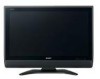
Sharp 45D40U Service Manual
Sharp 45D40U - LC - 45" LCD TV Manual
 |
UPC - 074000363199
View all Sharp 45D40U manuals
Add to My Manuals
Save this manual to your list of manuals |
Sharp 45D40U manual content summary:
- Sharp 45D40U | Service Manual - Page 1
LC-40C45U SERVICE MANUAL No. S46S5LC40C45U LCD COLOR TELEVISION MODEL LC-40C45U In the interests of user-safety (Required by safety regulations in some countries) the set should be restored to its original condition and only parts identical to those specified should be used. OUTLINE This model - Sharp 45D40U | Service Manual - Page 2
KEYUnit AC INLET Unit POWER SUPPLY Unit LCD PANEL 45" WIDE LCD Panel Module Unit CABINET AND MECHANICAL PARTS Please refer to a Parts list. PACKING PARTS AND ACCESSORIES Please refer to a Parts list. Service Manual LC-45D40U DUNTKD640FM07 DUNTKD641FM07 DUNTKD643FM07 DUNTKD716FM07 DUNTKD726FM07 - Sharp 45D40U | Service Manual - Page 3
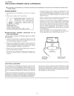
CONNECT TO KNOWN EARTH GROUND SAFETY NOTICE Many electrical and mechanical parts in LCD color television have special safety-related characteristics. For continued protection, replacement parts must be identical to those used in the original circuit. These characteristics are often not - Sharp 45D40U | Service Manual - Page 4
LC-40C45U PRECAUTIONS A PRENDRE LORS DE LA REPARATION Ne peut effectuer la réparation qu' un technicien spécialisé qui s'est parfaitement accoutumé à toute vérification de sécurité et - Sharp 45D40U | Service Manual - Page 5
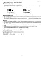
LC-40C45U „Employing lead-free solder • "PWBs" of this model employs lead-free solder. The LF symbol indicates lead-free solder, and is attached on the PWBs and service manuals off the power of the replacing parts with polarity indication on the PWB silk. Lead-free wire solder for servicing Part - Sharp 45D40U | Service Manual - Page 6
LC-40C45U LCC-H40AC45PUTER 1. SPECIFICATIONS [1] SPECIFICATIONS Service Manual Item LCD panel Model: LC-40C45U 45" Advanced Super View & BLACK TFT LCD Number of dots 3,147,264 dots (1366 x 768 x 3 dots) TV Function TV-standard (CCIR) Receiving VHF/UHF Channel CATV American TV Standard ATSC/ - Sharp 45D40U | Service Manual - Page 7
names TV (Rear) INPUT 4 terminals INPUT 5 terminal DIGITAL AUDIO OUTPUT terminal Antenna/Cable in 2 - 1 Service Manual Remote control sensor OPC sensor* POWER indicator** OPC indicator* INPUT 3 terminals AUDIO OUTPUT terminals INPUT 1 terminals INPUT 2 terminals AC INPUT terminal LC-40C45U - Sharp 45D40U | Service Manual - Page 8
LC-40C45U 2 - 2 Part names Remote control unit 1 14 2 3 4 5 6 7 8 9 10 11 12 13 1 TV POWER: Switch the TV power on or enters standby mode. 2 DISPLAY: Display the channel information. 3 SOURCE POWER: Turns the power of the external equipment on and off. 4 External equipment operational buttons: - Sharp 45D40U | Service Manual - Page 9
adjustment settings Menu items List of menu items to help you with operations Picture OPC Backlight Contrast Brightness Color Tint Sharpness Advanced Color Temp. Black 3D-Y/C Monochrome Film Mode Range of OPC Treble Bass Balance Surround Audio No Signal Off No Operation Off Power Control Setup - Sharp 45D40U | Service Manual - Page 10
LC-40C45U LCC-H40AC45PUTER 3. DIMENSIONS [1] DIMENSIONS Service Manual Unit: inch/(mm) 243/32 (612) 4353/64 (1113) 3861/64 (989.1) 43/32 (104) 4 /31 32 (126) 2159/64 (556.7) 1843/64 (474) 3163/64 (812) 2957/64 (759) 77/8 (200) 121/64 (305) 23/32 (53) 77/8 (200) 61 3 /64 (100) 3 - 1 - Sharp 45D40U | Service Manual - Page 11
LC-40C45U PARTS GUIDE No. S46S5LC40C45U MODEL LC-40C45U ★ MARK: SPARE PARTS-DELIVERY SECTION CONTENTS [1] PRINTED WIRING BOARD ASSEMBLIES (NOT REPLACEMENT ITEM) [2] LCD PANEL (NOTE: THE PARTS HERE SHOWN ARE SUPPLIED AS AN ASSEMBLY BUT NOT INDEPENDENTLY.) [3] CABINET AND MECHANICAL PARTS - Sharp 45D40U | Service Manual - Page 12
ASSEMBLIES (NOT REPLACEMENT ITEM) N DUNTKD640FM14 - N DUNTKD641FM14 - N DUNTKD643FM14 - N DUNTKD716FM14 - N DUNTKD726FM14 - N RDENCA166WJQZ BU R MAIN Unit X LED Unit X IF Unit X KEYUnit X AC INLET Unit X POWER SUPPLY Unit [2] LCD PANEL (NOTE: THE PARTS HERE SHOWN ARE SUPPLIED AS AN - Sharp 45D40U | Service Manual - Page 13
[3] CABINET AND MECHANICAL PARTS LC-40C45U 52 53 33 13 14 53 33 3-1 50 10 56 3 3-2 3-4 3-3 47 63 44 48 43 46 1 1-6 1-3 56 6 1-1 1-2 23 54 41 57 15 55 49 21 51 4 4-1 31 4-2 4-3 45 66 58 59 2 2-1 52 5-1 2-2 27 55 50 26 50 20 5-2 16 5 5-5 5-3 5-4 5-3 5-6 5-3 5-5 5-4 18 - Sharp 45D40U | Service Manual - Page 14
X Stand Support Ass'y - Support Cover - Stand Support - Screw Guide, x4 X Stand Base Ass'y - Stand Base Cover - Base Angle - LEG Cushion-A, x4 - LEG Cushion-B, x4 X Screw, x14 - Stand Label X 45" WIDE LCD Panel Module Unit R MAIN Unit X LED Unit X IF Unit X KEYUnit X AC INLET Unit X POWER SUPPLY - Sharp 45D40U | Service Manual - Page 15
AH R Connecting Cord (KM) R Connecting Cord (PD) R Connecting Cord (FD) DESCRIPTION LC-40C45U [4] SUPPLIED ACCESSORIES X1 Cable Clamp X2 Cable Band X4 AC Cord X5 Remote Control Unit X9 Operation manual X3 Stand Ass'y X6 X11 X7 X12 X8 X10 NO. PARTS CODE PRICE NEW RANK MARK - Sharp 45D40U | Service Manual - Page 16
LC-40C45U [5] PACKING PARTS (NOT REPLACEMENT ITEM) S8 S5 S7 S8 S9 S3 S6 S8 S8 S10 S2 S4 S1 S4 6 - Sharp 45D40U | Service Manual - Page 17
Unit (PE) J 6pins L=1000mm, Main to Power Unit (PD) J 4-8pins L=1000mm, Main to Inverter Unit (LB) J 14-14pins L=1000mm, Power to Inverter Unit (LA) J 32pins L=1000mm, Main to Controller Unit (LV) J 7pins L=1000mm, Main to Controller Unit (SH) J 5pins L=1000mm, Main to Power Unit (FD) LC-40C45U 7 - Sharp 45D40U | Service Manual - Page 18
LC-40C45U COPYRIGHT 2006 BY SHARP CORPORATION ALL RIGHTS RESERVED. No part of this publication may be reproduced, stored in a retrieval system, and Production Information Design: Japan Production: SEMEX SY. KD SHARP CORPORATION AV Systems Group CS Promotion Center Yaita, Tochigi 329-2193, Japan
-
 1
1 -
 2
2 -
 3
3 -
 4
4 -
 5
5 -
 6
6 -
 7
7 -
8
-
9
-
10
-
11
-
12
-
13
-
14
-
15
-
16
-
17
-
18
 |
 |

SERVICE MANUAL
LC-40C45U
No. S46S5LC40C45U
LC-40C45U
MODEL
CONTENTS
Parts marked with "
" are important for maintaining the safety of the set. Be sure to replace these parts with specified ones for maintaining the
safety and performance of the set.
This document has been published to be used for
after sales service only.
The contents are subject to change without notice.
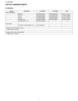
LIST OF CHANGED PARTS
LC-40C45U
........................................................
i
SAFETY PRECAUTION
IMPORTANT SERVICE SAFETY PRE-
CAUTION
..........................................................
ii
PRECAUTIONS A PRENDRE LORS DE
LA REPARATION
.............................................
iii
PRECAUTIONS FOR USING LEAD-FREE
SOLDER
..........................................................
iv
CHAPTER 1. SPECIFICATIONS
[1]
SPECIFICATIONS
........................................
1-1
CHAPTER 2. OPERATION MANUAL
[1]
OPERATION MANUAL
.................................
2-1
CHAPTER 3. DIMENSIONS
[1]
DIMENSIONS
...............................................
3-1
Parts Guide
TopPage
LCD COLOR TELEVISION
In the interests of user-safety (Required by safety regulations in some countries) the set should
be restored to its original condition and only parts identical to those specified should be used
.
OUTLINE
This model is based on the LC-45D40U and is changed some parts. This Service Manual covers the modifications
alone. For the other points, refer to the LC-37/45D40U Service Manual.