Sharp AX1200K RK-12S30 Installation Instructions - Page 8
Step 9, Frame Assembly Installation
 |
UPC - 074000617650
View all Sharp AX1200K manuals
Add to My Manuals
Save this manual to your list of manuals |
Page 8 highlights
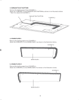
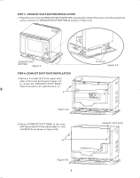
4 Secure EXHAUST DUCT BOTTOM to the shelf with 2 SCREWS (B) as shown in Figures 8-B. SCREW (B) Figure 8-B STEP 9: FRAME ASSEMBLY INSTALLATION 1 Attach FRAME ASSEMBLY and tighten 4 SCREWS (C) as shown in Figure 9 and Figure 9-A. SCREW (C) SCREW (C) SCREW (C) SCREW (C) BOTTOM PANEL of FRAME ASSEMBLY FRAME ASSEMBLY Figure 9 Figure 9-A Pull bottom panel of FRAME ASSEMBLY toward you to remove or replace the drip tray. For any other assistance or information about this product, please call SHARP's Customer Assistance Center 1-800-BE-SHARP. ® SHARP ELECTRONICS CORPORATION Sharp Plaza, Mahwah, NJ 07495-1163 8
-
 1
1 -
2
-
 3
3 -
 4
4 -
 5
5 -
 6
6 -
 7
7 -
 8
8
 |
 |

8
4
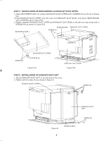
Secure EXHAUST DUCT BOTTOM to the shelf with 2 SCREWS (B) as shown in Figures 8-B.
STEP 9:
FRAME ASSEMBLY INSTALLATION
1
Attach FRAME ASSEMBLY and tighten 4 SCREWS (C) as shown in Figure 9 and Figure 9-A.
Pull bottom panel of FRAME ASSEMBLY toward you to remove or replace the drip tray.
For any other assistance or information about this product, please call SHARP's Customer Assistance Cen-
ter 1-800-BE-SHARP.
FRAME
ASSEMBLY
Figure 8-B
SCREW (B)
SCREW (C)
SCREW (C)
SCREW (C)
SCREW (C)
Figure 9
Figure 9-A
®
SHARP ELECTRONICS CORPORATION
Sharp Plaza, Mahwah, NJ 07495-1163
BOTTOM PANEL of
FRAME ASSEMBLY