Sharp CD-E55 Service Manual - Page 15
Notes On Schematic Diagram, Types Of Transistor And Led
 |
View all Sharp CD-E55 manuals
Add to My Manuals
Save this manual to your list of manuals |
Page 15 highlights
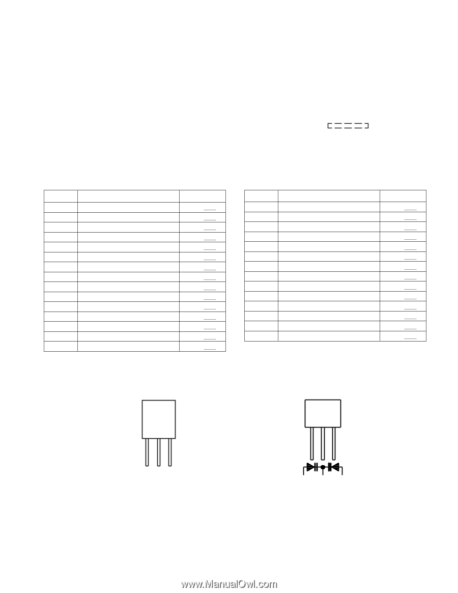
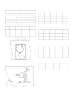
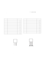
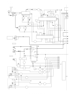
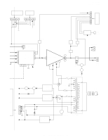
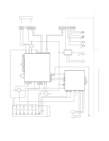
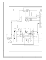
NOTES ON SCHEMATIC DIAGRAM CD-E500 CD-E55/E44 • Resistor: To differentiate the units of resistors, such symbol as K and M are used: the symbol K means 1000 ohm and the symbol M means 1000 kohm and the resistor without any symbol is ohm-type resistor. Besides, the one with "Fusible" is a fuse type. • Capacitor: To indicate the unit of capacitor, a symbol P is used: this symbol P means pico-farad and the unit of the capacitor without such a symbol is microfarad. As to electrolytic capacitor, the expression "capacitance/withstand voltage" is used. (CH), (TH), (RH), (UJ): Temperature compensation (ML): Mylar type (P.P.): Polypropylene type • Schematic diagram and Wiring Side of P.W.Board for this model are subject to change for improvement without prior notice. • The indicated voltage in each section is the one measured by Digital Multimeter between such a section and the chas- sis with no signal given. 1. In the tuner section, indicates AM indicates FM stereo 2. In the main section, a tape is being played back. 3. In the deck section, a tape is being played back. 4. In the power section, a tape is being played back. 5. In the CD section, the CD is stopped. • Parts marked with " 1 " ( ) are important for maintaining the safety of the set. Be sure to replace these parts with specified ones for maintaining the safety and performance of the set. REF. NO SW1 SW401 SW402 SW403 SW404 SW701 SW702 SW703 SW704 SW705 SW706 SW707 SW708 SW709 SW710 DESCRIPTION PICKUP IN DISC UP/DOWN OPEN/CLOSE DISC NO. DISC 1 X-BASS/DEMO POWER ON/STAND-BY OPEN/CLOSE DISK SKIP VIDEO/AUX TAPE PRESET DOWN PLAY/REPEAT PRESET UP STOP POSITION ON-OFF ON-OFF ON-OFF ON-OFF ON-OFF ON-OFF ON-OFF ON-OFF ON-OFF ON-OFF ON-OFF ON-OFF ON-OFF ON-OFF ON-OFF REF. NO SW711 SW712 SW713 SW714 SW715 SW719 SW720 SW721 SW722 SW723 SW724 SW801 SW802 SW803 DESCRIPTION MEMORY/SET TUNING/TIME DOWN TUNING/TIME UP TIMER/SLEEP CLOCK EQUALIZER VOLUME UP VOLUME DOWN TUNER(BAND) CD REC/PAUSE TAPE2 INITIALIZE TAPE1 INITIALIZE TAPE2 REC POSITION ON-OFF ON-OFF ON-OFF ON-OFF ON-OFF ON-OFF ON-OFF ON-OFF ON-OFF ON-OFF ON-OFF ON-OFF ON-OFF ON-OFF TYPES OF TRANSISTOR AND LED FRONT VIEW EC B (S) (G) (D) (1) (2) (3) HSB562 C KSA1015 GR HSC1609 GR KSA1271 Y KRA102 M KSC1815 GR KRA107 M KSC3203 Y KRC102 M SSC1674 C KRC104 M 2SC2001 K KRC107 M - 15 - 123 KDV147B SVC348S
-
 1
1 -
2
-
3
-
4
-
5
-
6
-
7
-
8
-
9
-
 10
10 -
 11
11 -
 12
12 -
 13
13 -
 14
14 -
 15
15 -
 16
16 -
 17
17 -
 18
18 -
 19
19 -
 20
20 -
21
-
22
-
23
-
24
-
25
-
26
-
27
-
28
-
29
-
30
-
31
-
32
-
33
-
34
-
35
-
36
-
37
-
38
-
39
-
40
-
41
-
42
-
43
-
44
-
45
-
46
-
47
-
48
-
49
-
50
-
51
-
52
-
53
-
54
-
55
-
56
-
57
-
58
-
59
-
60
 |
 |