Sharp CV-PD13PX CV-P12PX CV-P13PX CV-PD13PX Operation Manual - Page 21
Installation of the exhaust hose
 |
UPC - 074000662612
View all Sharp CV-PD13PX manuals
Add to My Manuals
Save this manual to your list of manuals |
Page 21 highlights
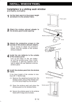
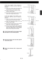
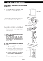
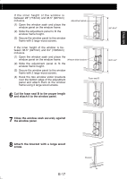
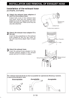
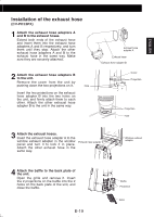
ENGLISH Installation of the exhaust hose (CV-PD13PX) 1 Attach the exhaust hose adapters A and B to the exhaust hoses. Extend both ends of the exhaust hose and insert them into the exhaust hose adapters A and B respectively, and turn them until they stop. Attach the other exhaust hose adapters A and B to the exhaust hose in the same way. Make sure they are securely attached. 2 Attach the exhaust hose adapters B to the unit. Remove the cover from the unit by pushing down the two projections on it. Hole Insert the two projections on the exhaust hose adapter B into the two holes on the unit, and firmly attach them to each other. Attach the other exhaust hose adapter B to the unit in the same way. Exhaust hose adapter A Exhaust hose Exhaust hose adapter B Cover Projection Projection Hole 3 Attach the exhaust hoses. Insert the exhaust hose adapter A to the window exhaust adapter in the window panel and turn it to lock it in place. Attach the other exhaust hose in the same way. Exhaust hose adapter A Window exhaust adapter 4 Attach the baffle to the back plate of the unit. Open the grille and remove it. Insert the 2 projections on the baffle into the 2 holes on the back plate of the unit, and Hole close the baffle. E-19 Baffle Projection Grille
-
 1
1 -
2
-
3
-
4
-
5
-
6
-
7
-
8
-
9
-
10
-
11
-
12
-
13
-
14
-
15
-
 16
16 -
 17
17 -
 18
18 -
 19
19 -
 20
20 -
 21
21 -
 22
22 -
 23
23 -
 24
24 -
 25
25 -
 26
26 -
27
-
28
-
29
-
30
-
31
-
32
-
33
-
34
 |
 |
