Sharp CV10NH CV-10NH Operation Manual - Page 10
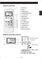
Part Names - remote
 |
UPC - 074000662377
View all Sharp CV10NH manuals
Add to My Manuals
Save this manual to your list of manuals |
Page 10 highlights
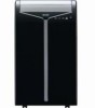
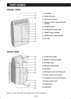
PART NAMES FRONT VIEW 1 1 Air Outlet 2 2 Vertical louvers 3 3 Horizontal louvers 4 Remote control signal receiver 4 window 5 5 POWER Button 6 6 OPERATION Lamp (red) 7 7 TIMER Lamp (orange) 8 9 8 MEGA COOL Lamp (green) 9 9 Air inlet 9 REAR VIEW 0 0 Exhaust air outlet q q Window exhaust adapter w w Exhaust hose e e Remote control hook r t r Air filters y t Drainage nozzle and stopcock y Power supply cord hooks u Drainpipe nozzle and stopcock u i Power supply cord i o Power plug o p p Casters(4) NOTE: Actual unit might vary slightly from above illustration. E-8
-
 1
1 -
2
-
3
-
4
-
 5
5 -
 6
6 -
 7
7 -
 8
8 -
 9
9 -
 10
10 -
 11
11 -
 12
12 -
 13
13 -
 14
14 -
 15
15 -
16
-
17
-
18
-
19
-
20
-
21
-
22
-
23
-
24
-
25
-
26
-
27
-
28
-
29
-
30
-
31
-
32
-
33
-
34
-
35
-
36
-
37
-
38
-
39
-
40
-
41
-
42
-
43
-
44
-
45
-
46
-
47
-
48
-
49
-
50
-
51
-
52
-
53
-
54
-
55
-
56
-
57
-
58
-
59
-
60
 |
 |

PART NAMES
1
Air Outlet
2
Vertical louvers
3
Horizontal louvers
4
Remote control signal receiver
window
5
POWER Button
6
OPERATION Lamp (red)
7
TIMER Lamp (orange)
8
MEGA COOL Lamp (green)
9
Air inlet
REAR VIEW
NOTE:
Actual unit might vary slightly from above illustration.
FRONT VIEW
0
Exhaust air outlet
q
Window exhaust adapter
w
Exhaust hose
e
Remote control hook
r
Air
fi
lters
t
Drainage nozzle and stopcock
y
Power supply cord hooks
u
Drainpipe nozzle and stopcock
i
Power supply cord
o
Power plug
p
Casters(4)
E-8
1
2
3
4
5
6
7
8
9
9
9
0
q
w
e
r
t
y
u
i
o
p