Sharp ER-A450T Dealer Knowledge Book - Page 8
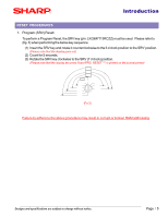
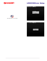
Placing the ER-A450T into the Receive State
 |
View all Sharp ER-A450T manuals
Add to My Manuals
Save this manual to your list of manuals |
Page 8 highlights
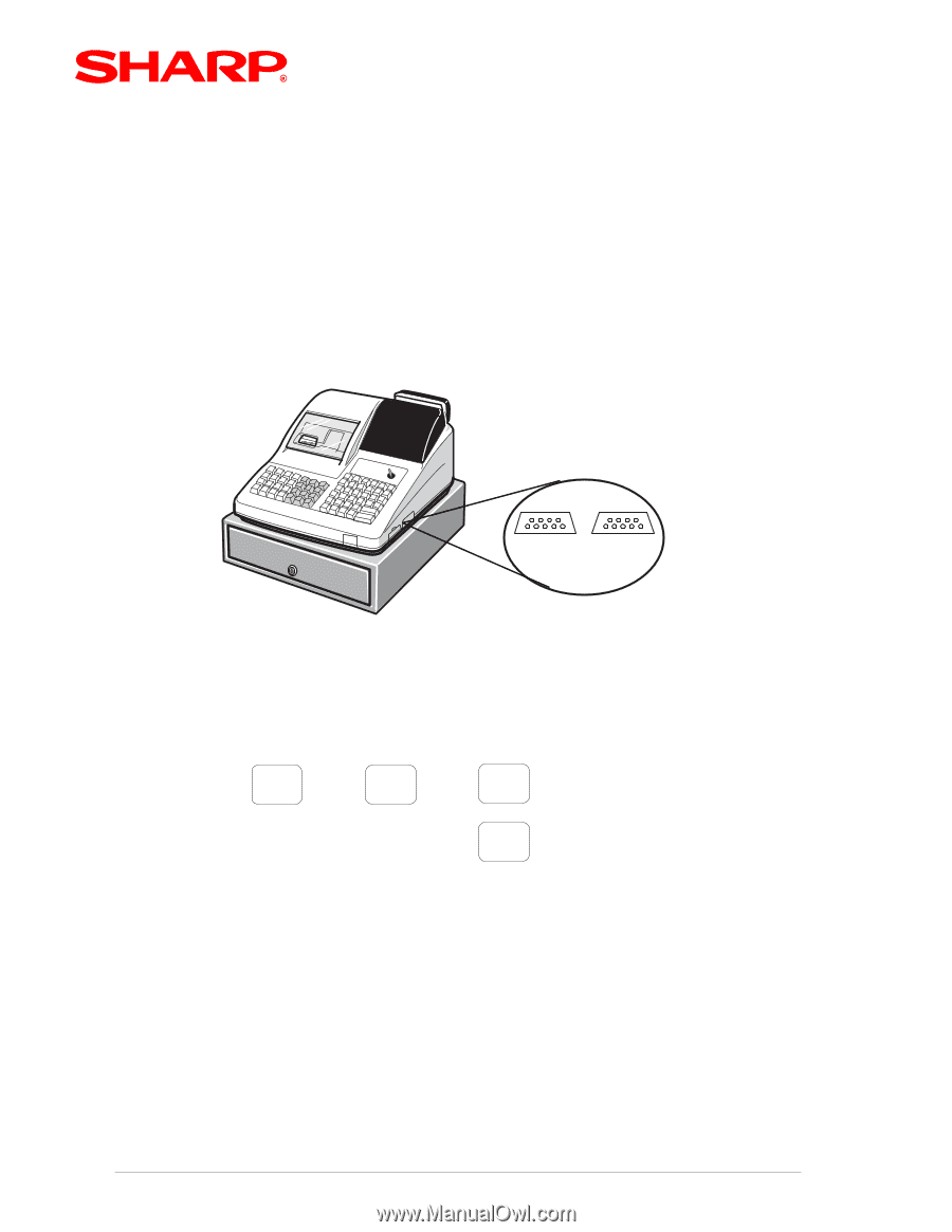
ER-A450T Setup 2. The ER-A450T SIO Function: In addition to setting the graphics logo print control, the image data may be sent to the ER-A450T using the SIO Function. (1) Connection at the ER-A450T; The Program Back up/Restore (SIO) function has been fixed to port-2 (Channel #1) of the ER-A450T as shown below: X Channel No.: Port 1(CH8) Channel No.: Port 2(CH1) 3 When using the SIO function, the connection for the cable is port-2 (CH#1) (FIG.5) (2) Placing the ER-A450T into the Receive State; 4 . 4 4 998 @/ FOR CA/AT 4 SBTL (Auto baud rate detection - SRV job#903-A) Designs and specifications are subject to change without notice. Page / 7
-
 1
1 -
2
-
 3
3 -
 4
4 -
 5
5 -
 6
6 -
 7
7 -
 8
8 -
 9
9 -
 10
10 -
 11
11 -
 12
12 -
 13
13 -
14
-
15
-
16
-
17
-
18
 |
 |
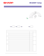
ER-A450T Setup
Page
/
7
Designs and specifications are subject to change without notice.
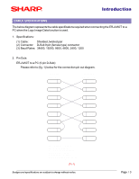
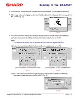
2.
The ER-A450T SIO Function:
In addition to setting the graphics logo print control, the image data may be sent to the ER-A450T
using the SIO Function.
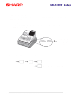
(1)
Connection at the ER-A450T;
The Program Back up/Restore (SIO) function has been fixed to port-2 (Channel #1) of the
ER-A450T as shown below:
(F
IG
.5)
Channel No.:
Port 1(CH8)
Channel No.:
Port 2(CH1)
3
When using the SIO
function, the connection
for the cable is port-2
(CH#1)
X
998
.
4
4
4
@/
FOR
4
CA/AT
SBTL
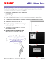
(Auto baud rate detection - SRV job#903-A)
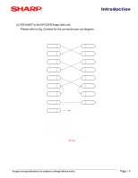
(2)
Placing the ER-A450T into the Receive State;