Sharp HT-CN300S Service Manual - Page 6
Disassembly
 |
View all Sharp HT-CN300S manuals
Add to My Manuals
Save this manual to your list of manuals |
Page 6 highlights
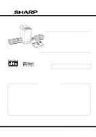
HT-CN300 DISASSEMBLY Caution on Disassembly Follow the below-mentioned notes when disassembling the unit and reassembling it, to keep it safe and ensure excellent performance: 1. Be sure to remove the power supply plug from the wall outlet before starting to disassemble the unit. 2. Take off nylon bands or wire holders where they need to be removed when disassembling the unit. After servicing the unit, be sure to rearrange the leads where they were before disassembling. 3. Take sufficient care on static electricity of integrated circuits and other circuits when servicing. HT-CN300 Top Cover A Top Cover B (A1)x2 ø3x8mm (D1)x6 ø3x8mm (B1)x2 ø2.5x12mm LCD Cover HT-CN300 STEP REMOVAL PROCEDURE FIGURE 1 Top Cover B 1. Screw A1) x2 6-1 2 LCD Cover 1. Hexagon Screw ...... (B1) x2 6-1 3 Top Cover A/ LCD PWB 1. Screw C1) x4 6-2 2. Flat Cable C2) x3 3. Screw C3) x4 4 Back Cover L/R/ 1. Screw D1) x25 6-1, 7-1 Rear Panel 5 DSP PWB 1. Screw E1) x2 7-2 2. Socket E2) x1 3. Flat Cable E3) x4 4. PWB Holder E4) x2 6 Subwoofer Stand/ 1. Screw F1) x4 7-2 PWB Unit 2. Screw F2) x2 3. Socket F3) x1 7 Video PWB 1. Screw G1) x3 7-3 2. Socket G2) x2 8 Audio PWB 1. Screw H1) x2 7-3 9 AMP. PWB 1. Screw J1) x6 7-3 2. Socket J2) x4 10 Speaker PWB 1. Screw K1) x1 7-3 11 Subwoofer 1. Screw L1) x4 7-2 Back Cover R Back Cover L Figure 6-1 (C1)x2 ø4x20mm (C2)x3 Top Cover A DSP PWB (C1)x2 ø4x12mm LCD PWB (C3)x4 ø3x8mm Figure 6-2 - 6 -
-
 1
1 -
 2
2 -
 3
3 -
 4
4 -
 5
5 -
 6
6 -
 7
7 -
 8
8 -
 9
9 -
 10
10 -
 11
11 -
 12
12 -
13
-
14
-
15
-
16
-
17
-
18
-
19
-
20
-
21
-
22
-
23
-
24
-
25
-
26
-
27
-
28
-
29
-
30
-
31
-
32
-
33
-
34
-
35
-
36
-
37
-
38
-
39
-
40
-
41
-
42
-
43
-
44
-
45
-
46
-
47
-
48
-
49
-
50
-
51
-
52
-
53
-
54
-
55
-
56
 |
 |
