Sharp KB5121KS KB-5121KS , KB-5121KK , KB-5121KW Installation Instructions - Page 5
Installation Manual - microwave drawer
 |
UPC - 074000615700
View all Sharp KB5121KS manuals
Add to My Manuals
Save this manual to your list of manuals |
Page 5 highlights
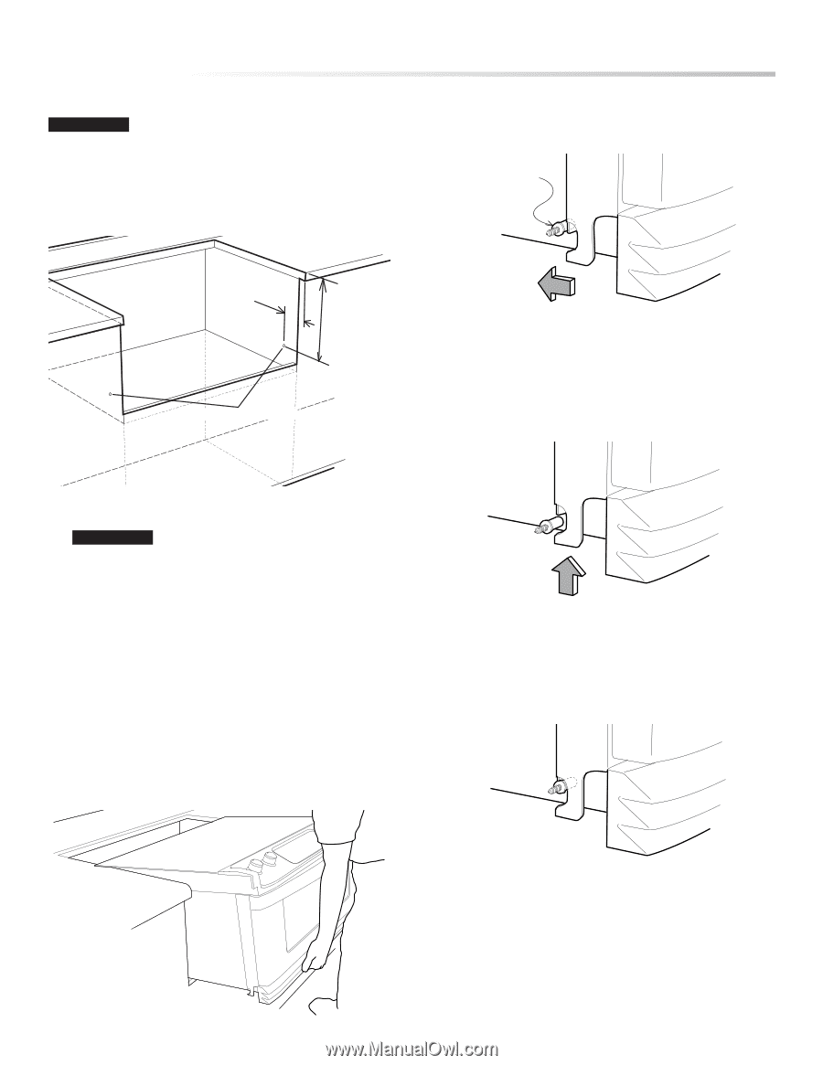
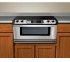
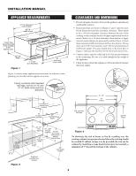
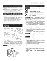
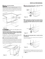
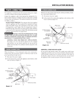
C INSTALL THE STOP SCREWS IMPORTANT Confirm all cut-out openings and clearances as indicated on page 2 before installing the appliance. These two stop screws prevent the appliance from sliding out of position during operation. Attach the stop screws (supplied in the screw bag) to the right and left sides of the cabinet opening as specified. See Figure 10. Use a 1/16" drill bit to pre-drill holes. INSTALLATION MANUAL F PUSH THE UNIT BACK UNTIL IT HITS THE STOP SCREWS INSTALLED IN STEP "C" See Figure 12. Stop screw installed in step "C" 2 1/4" from front edge of countertop 13 7/8" from top of counter stop screw locations Figure 12 G LIFT THE FRONT OF THE UNIT UP SLIGHTLY (ABOUT 1/2") AND PUSH BACK UNTIL THE SLOTS ON THE MOUNTING BRACKET ENGAGE THE STOP SCREWS. See Figure 13. Figure 10 D IMPORTANT Do not lift or move this appliance by the Microwave Drawer handle. POSITION THE APPLIANCE IN FRONT OF THE OPENING AND PLACE THE ELECTRICAL CONDUIT CLOSE TO THE LOCATION OF THE JUNCTION BOX. If needed, drill a 1" hole in the cabinet side or bottom to allow the conduit access to the junction box. DO NOT CONNECT until installation of the appliance is complete in the cabinet. E PLACE THE APPLIANCE INTO OPENING It is suggested that two people lift the appliance into place, carefully setting the side metal flanges under the cooktop glass on the edges of the countertop opening. Check that the appliance clears the cabinet face frame. Tilt the appliance as you slide it back so that it will clear. The unit will have to be pushed in until the front feet are behind the cabinet face frame. See Figure 11. Figure 13 H LOWER THE APPLIANCE UNTIL IT RESTS ON THE COUNTERTOP. Confirm that the slots on the mounting bracket have engaged the stop screws. See Figure 14. Figure 11 Figure 14 If the cooktop does not fit properly on the counter top, the mounting bracket may not be positioned properly on the stop screws. To correct, slide the appliance out one inch and follow instructions from F above. 5
-
 1
1 -
 2
2 -
 3
3 -
 4
4 -
 5
5 -
 6
6 -
 7
7 -
 8
8
 |
 |