Sharp PN-A601 PN-A601 Professional LCD Monitor Operation Manual - Page 10
Part Names - speakers
 |
View all Sharp PN-A601 manuals
Add to My Manuals
Save this manual to your list of manuals |
Page 10 highlights
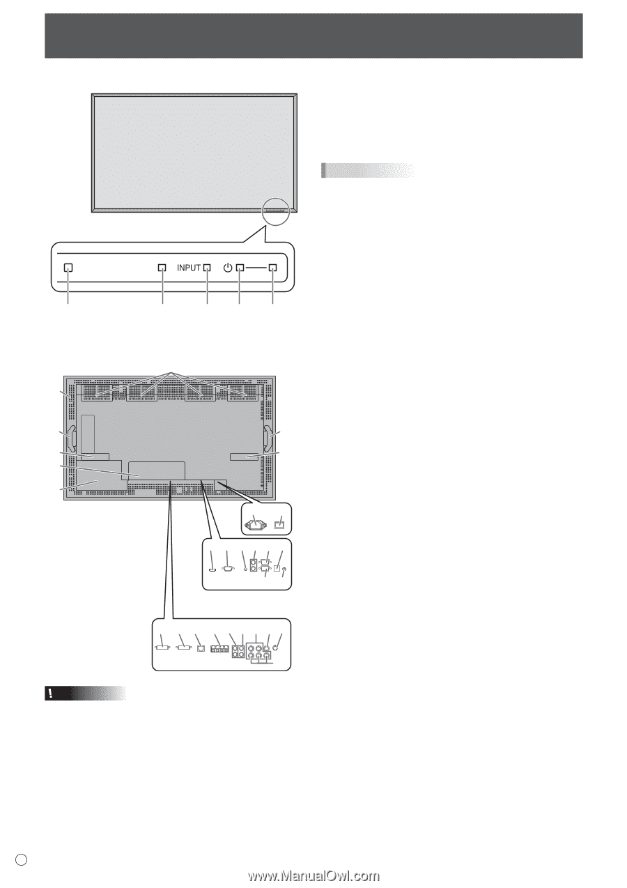
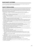
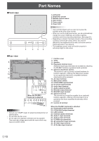
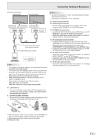
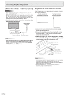
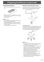
nFront view 2 Part Names 1 3 4 5 6 1. LCD panel 2. Brightness sensor 3. Remote control sensor 4. Input switch 5. Power switch 6. Power LED TIPS • Use a pointed object such as a pen tip to press the switches at the front of the monitor. • When you use the brightness sensor, you can automatically change the screen brightness according to lighting conditions and the surrounding brightness. (See page 24.) • Depending on where it has been placed or the surrounding conditions, the remote control sensor box may be affected by the brightness of the main unit screen and the brightness sensor may respond. • The brightness sensor may not function properly in extremely bright or dark areas. nRear view 7 8 9 9 7 7 10 11 12 13 14 15 16 17 18 20 19 21 When the PN-ZB01 (optional) is attached 22 23 24 25 26 27 28 30 31 29 Caution • Consult your SHARP dealer for attachment/detachment of optional parts. • Do not block the fan cover. • Do not open the expansion terminal cover by yourself. There are high voltage parts inside the cover which may cause an electric shock. 7. Fan/Fan cover 8. Vents 9. Handles 10. Expansion terminal cover Additional input/output terminals are available by attaching the PN-ZB01 interface expansion board (optional). 11. Optional attachment section This section is used to connect optional hardware for function expansion. Offering this attachment location is not a guarantee that future compatible hardware attachments will be released. 12. AC input terminal 13. Main power switch 14. PC/AV HDMI input terminal 15. PC D-sub input terminal 16. Audio input terminal 17. Audio output terminals 18. RS-232C output terminal 19. RS-232C input terminal 20. Optional terminal This terminal is provided for possible future (optional) function expansion. Offering of this terminal is not a guarantee that future expanded functionality will be provided. 21. Control kit terminal When the PN-ZB01 (optional) is attached 22. PC/AV DVI-D input terminal 23. PC/AV DVI-D output terminal 24. LAN terminal 25. External speaker terminals 26. Audio 1 input terminals 27. Audio 2 input terminals 28. PC RGB input terminals 29. AV component input terminals 30. AV video input terminal 31. AV S-video input terminal E 10
-
 1
1 -
2
-
3
-
4
-
 5
5 -
 6
6 -
 7
7 -
 8
8 -
 9
9 -
 10
10 -
 11
11 -
 12
12 -
 13
13 -
 14
14 -
 15
15 -
16
-
17
-
18
-
19
-
20
-
21
-
22
-
23
-
24
-
25
-
26
-
27
-
28
-
29
-
30
-
31
-
32
-
33
-
34
-
35
-
36
-
37
-
38
-
39
-
40
-
41
-
42
-
43
-
44
-
45
-
46
-
47
-
48
-
49
-
50
-
51
-
52
-
53
-
54
-
55
-
56
-
57
-
58
-
59
-
60
 |
 |