Sharp PN-TPC1 PN-TPC1 Signage Controller User Guide - Page 7
Put the AC power adapter, Install the PN-TPC1, Finish
 |
View all Sharp PN-TPC1 manuals
Add to My Manuals
Save this manual to your list of manuals |
Page 7 highlights
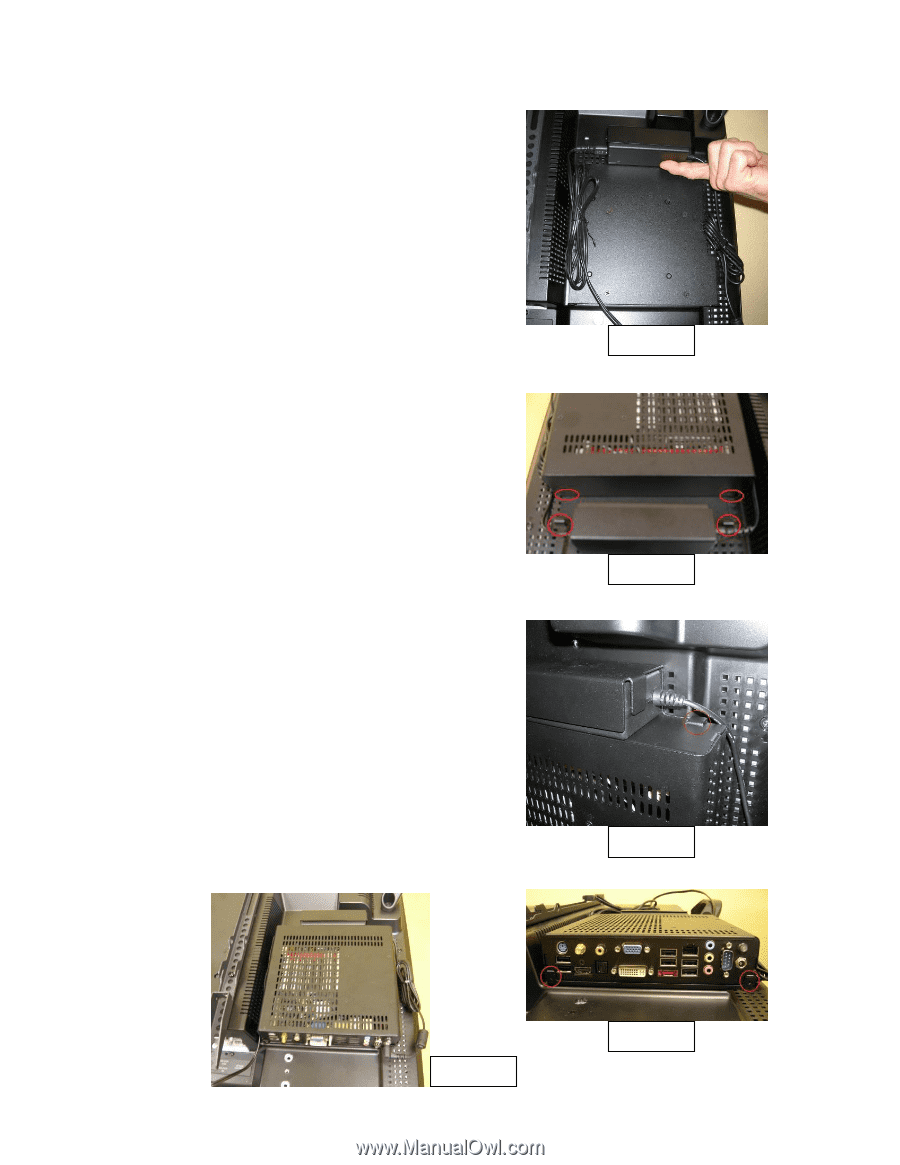
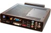
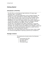
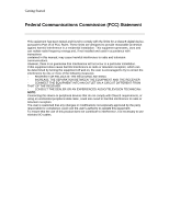
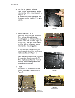
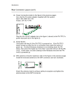
Installation 4. Put the AC power adapter Place the AC power adapter into the holder on top of the mounting plate as in Figure 3. AC power cord faces inside and the DC power cord to the PN-TPC1 faces outside. 5. Install the PN-TPC1 If you look at the top side of the PNTPC1 before sliding it into the mounting plate as in Figure 4, there are two small slits near the edges on the PN-TPC1 and two small fingers on either side of AC power adapter holder on the mounting plate. As you slide the PN-TPC1 into the mounting plate, insert the two fingers into these slits as in Figure 5. There are two fingers on the bottom of the mounting plate to catch the PNTPC1 in place as shown in Figure 6, and they need to be tightened with two include M3 screws. 6. Finish Plug in the DC power cord into the PN-TPC1's power connector as in Figure 7. Figure 3 Figure 4 Figure 5 Figure 7 Figure 6
-
 1
1 -
 2
2 -
 3
3 -
 4
4 -
 5
5 -
 6
6 -
 7
7 -
 8
8 -
 9
9 -
 10
10 -
 11
11 -
 12
12 -
13
 |
 |