Sharp PN-UH701 PN-UH601 PN-UH701 Quick Start Setup Guide - Page 27
Setting the TV on the Wall, For SHARP dealer and service engineers - dimensions
 |
View all Sharp PN-UH701 manuals
Add to My Manuals
Save this manual to your list of manuals |
Page 27 highlights
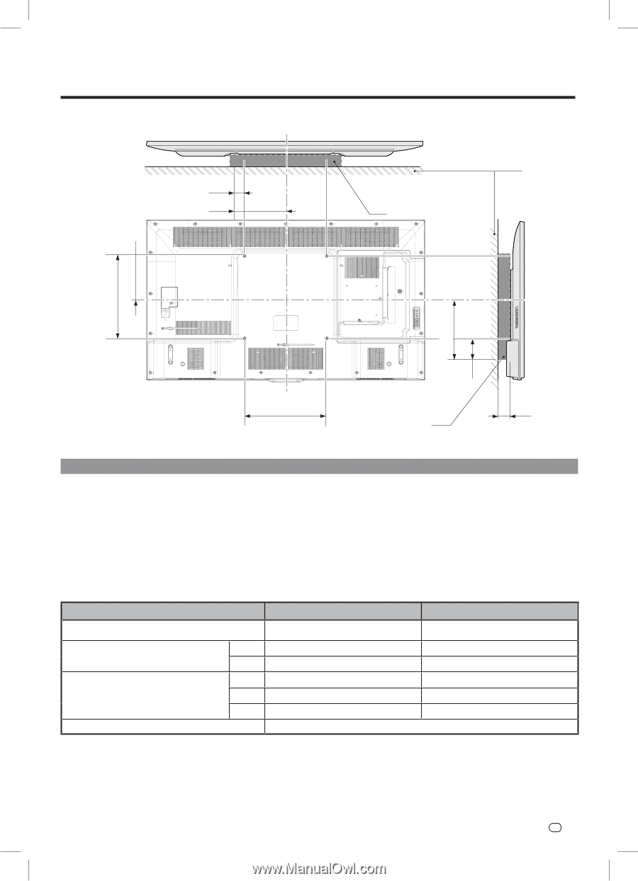
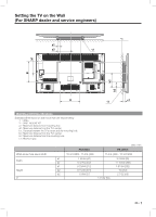
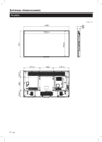
Setting the TV on the Wall (For SHARP dealer and service engineers) *1 a1 a2 *2 B b1 b2 b3 A *2 c1 Wall Mount Kit Specifications Standard dimensions for wall mount kits are shown below *1 : WALL *2 : WALL MOUNT KIT a1 : Maximum distance from mounting hole. a2 : Maximum distance from the TV's center. b1 : Distance between the TV's center and the mounting hole. b2 : Maximum distance from the TV's center. b3 : Maximum distance from the mounting hole. c1 : Minimum gap. VESA screw hole specs (A-B) Width Height c1 Unit : mm PN-UH601 PN-UH701 15 3/4 (400) - 15 3/4 (400) 15 3/4 (400) - 15 3/4 (400) a1 1 55/64 (47) 3 23/64 (85) a2 9 47/64 (247) 11 15/64 (285) b1 8 23/64 (212) 7 61/64 (202) b2 8 15/32 (215) 10 (254) b2 1 5/64 (27) 2 7/32 (56) 1 31/32 (50) EN - 7
-
 1
1 -
2
-
3
-
4
-
5
-
6
-
7
-
8
-
9
-
10
-
11
-
12
-
13
-
14
-
15
-
16
-
17
-
18
-
19
-
20
-
21
-
 22
22 -
 23
23 -
 24
24 -
 25
25 -
 26
26 -
 27
27 -
 28
28 -
 29
29 -
 30
30 -
 31
31 -
 32
32 -
33
-
34
-
35
-
36
-
37
-
38
-
39
-
40
-
41
-
42
-
43
-
44
 |
 |