Sharp R1214 R-1210 , R-1211 Operation Manual & Installation Instructions - Page 8
Preparation Of The Oven, Installation Hardware
 |
UPC - 074000611696
View all Sharp R1214 manuals
Add to My Manuals
Save this manual to your list of manuals |
Page 8 highlights
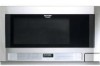
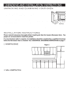
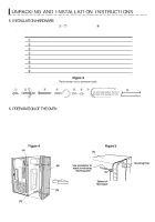
UNPACKING AND INSTALLATION INSTRUCTIONS 5 INSTALLATION HARDWARE The INSTALLATION HARDWARE items 1 - 7 are in a small bag. Item 8 is packed separately. All items are in a small carton packed below the oven. ITEM NAME 1 Wood Screw 5 X 30 mm 2 Toggle Bolt with nuts #10 - 24 X 50 mm 3 Top Cabinet Screw 5 X 60 mm 4 Power Cord Hanger 5 Tapping Screw 4 x 12 mm 6 Flat Washer 30 mm diameter 7 Grommet 8 Scale Plate QUANTITY 6 4 2 1 3 2 1 2 PART CODE XTSSD50P35000 LX-BZ0195WRE0 XBRSD50P60000 LX-MZB001MRE0 XOTSD40P12000 XWHSD50-16300 LBSHC0040MRE0 LANG-B003MRP0 Figure 3 Parts shown not to common scale. 6 PREPARATION OF THE OVEN 1. Turn oven on the side. See Figure 4. 2. Follow steps (A)-(D) to remove mounting plate from the back of the oven as shown in Figure 4. (A) Release mounting plate by pulling out the lever that is on the bottom of the oven. See Figure 5. (B) When lever is out, pull that side of the mounting plate away from the oven. See Figure 4. (C) Repeat step (A) on other side. (D) Repeat step (B) on other side. Figure 4 (A) Figure 5 (A) (B) Use screwdriver to assist in releasing mounting plate. Bottom of Microwave (D) Mounting Plate (C) 8
-
 1
1 -
2
-
 3
3 -
 4
4 -
 5
5 -
 6
6 -
 7
7 -
 8
8 -
 9
9 -
 10
10 -
 11
11 -
 12
12 -
 13
13 -
14
-
15
-
16
-
17
-
18
-
19
-
20
-
21
-
22
-
23
-
24
-
25
-
26
-
27
-
28
-
29
-
30
-
31
-
32
 |
 |
