Sharp XR-41XDM Service Manual - Page 14
Adjustment of ballast unit output power (lamp power), 2. Adjustment method
 |
View all Sharp XR-41XDM manuals
Add to My Manuals
Save this manual to your list of manuals |
Page 14 highlights
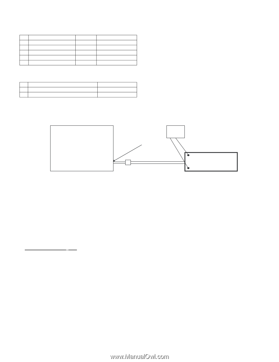
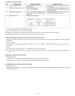
XR-40X/XR-41X/XG-F260X 1. Adjustment of ballast unit output power (lamp power) 1. List of parts requiring adjustment When replacing the following parts, adjust the ballast unit output power (lamp power). Part name 1 Cement resistor 2 Ballast Control PWB 3 Ballast microprocessor 4 5V regulator 5 Ballast Switching Control Ref No. R923 -- IC7707 IC7704 IC7701 Part code RR-FZA002WJZZ DUNTKE150WEF0 RH-iXC103WJZZQ VHiTA78L05F-1Y VHiM51995AF-1Y 2. Adjustment jigs The following jigs are required for adjusting the ballast unit output power (lamp power). Part name 1 Adjustment jig (resistance load 25 Ω) 2 Connecting cord (conversion cable) Part code RUNTZA018WJZZ QCNWKA020WJZZ 3. Ballast unit output power (lamp power) adjustment method Adjust the ballast unit output power (lamp power) in the following method. [Setting method] XR-40X XR-41X XG-F260X Projector Ballast Unit Lamp Cable Tester (Voltage) Connecting Cord (QCNWKA020WJZZ) TP1 Adjustment Jig (RUNTZA018WJZZ) TP2 2. Adjustment method 1) Unplug the ballast unit lamp cable of the projector from the lamp and connect the cable to the connecting cord (QCNWKA020WJZZ). 2) Connect the connecting cord (QCNWKA020WJZZ) to the adjustment jig (RUNTZA018WJZZ). 3) Connect TP1 of the adjustment jig (RUNTZA018WJZZ) to the negative terminal of the tester and TP2 to the positive terminal. 4) Turn on the projector. 5) Check the Lamp setting to "Bright". 6) Ageing the projector for 60 seconds or more. 7) Adjust the volume resistor (R7805) of the ballast control PWB (DUNTKE150WEF0) so that the voltage of the tester reaches 71±0.5V. Adjustment value: 71±0.5V CAUTION: (1) Caution for electric shock: Do not touch the test points TP1 and TP2 of the adjustment jig when supplying power since a high voltage and large current is applied to them. (2) Caution for heat: Be careful that the resistance load of the adjustment jig produces a high temperature when supplying power. (3) Connection of the lamp cable: Check that the lamp cable and connecting cord (QCNWKA020WJZZ) are connected securely. Poor connection may cause smoking or ignition due to arc discharge. 2 - 5
-
 1
1 -
2
-
3
-
4
-
5
-
6
-
7
-
8
-
 9
9 -
 10
10 -
 11
11 -
 12
12 -
 13
13 -
 14
14 -
 15
15 -
 16
16 -
 17
17 -
 18
18 -
 19
19 -
20
-
21
-
22
-
23
-
24
 |
 |