Snapper SP90 Operation Manual
Snapper SP90 Manual
 |
View all Snapper SP90 manuals
Add to My Manuals
Save this manual to your list of manuals |
Snapper SP90 manual content summary:
- Snapper SP90 | Operation Manual - Page 1
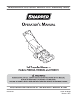
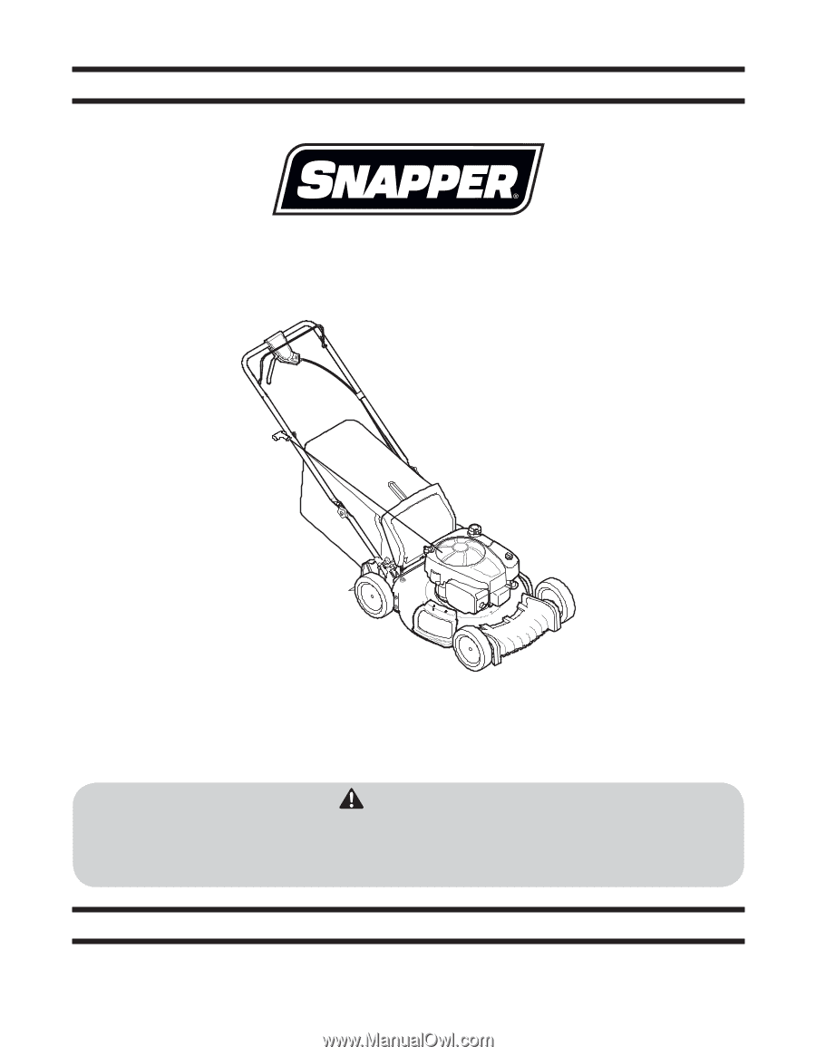
Operation Practices • Set-Up • Operation • Maintenance • Service • Troubleshooting • Warranty Operator's Manual Self Propelled Mower - Models 7800925, 7800928, and 7800931 WARNING READ AND FOLLOW ALL SAFETY RULES AND INSTRUCTIONS IN THIS MANUAL BEFORE ATTEMPTING TO OPERATE THIS MACHINE. FAILURE TO - Snapper SP90 | Operation Manual - Page 2
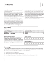
To The Owner 1 Thank you for purchasing a Snapper lawn mower. It was carefully engineered to provide excellent performance when properly operated and maintained. Please read this entire manual prior to operating the equipment. It instructs you how to safely and easily set up, operate and maintain - Snapper SP90 | Operation Manual - Page 3
job: bystanders, helpers and pets at least 75 feet from mower to mow grass. Do not use it for any other purpose performing an adjustment or repair the instructions and safe operation practices in this manual to parts or under the cutting deck. Contact with blade can amputate fingers, hands, toes and - Snapper SP90 | Operation Manual - Page 4
, bruises or sprains could result. 28. If situations occur which are not covered in this manual, use care and good judgement. Contact Customer Support for assistance or the name of the nearest service dealer. Slope Operation Slopes are a major factor related to slip and fall accidents, which can - Snapper SP90 | Operation Manual - Page 5
a foreign object, stop the engine, disconnect the spark plug wire and ground against the engine. Thoroughly inspect the mower for any damage. Repair the damage before starting and operating the mower. 8. Never attempt to make a wheel or cutting height adjustment while the engine is running. 9. Grass - Snapper SP90 | Operation Manual - Page 6
federal lands. A spark arrestor for the muffler is available through your nearest engine authorized service dealer or contact the service department at 1-800-317 ), and engine-to-engine variability. Due to manufacturing and capacity limitations, Briggs & Stratton may substitute an engine of higher - Snapper SP90 | Operation Manual - Page 7
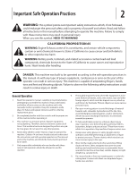
MANUAL(S) Read, understand, and follow all instructions in the manual(s) before attempting to assemble and operate DANGER - ROTATING BLADES Keep hands and feet away from rotating parts. DANGER - THROWN DEBRIS Remove objects that can be thrown by the blade in any direction. Wear safety glasses. - Snapper SP90 | Operation Manual - Page 8
on or behind the slope (e.g. a pole, building, fence, tree, etc.) 3. Align either side of the slope gauge with the object (See Figure 1 and Figure 2 ). 4. Adjust gauge up or down until the left corner touches the slope (See Figure 1 and Figure 2). 5. If there is a gap below the gauge, the slope is - Snapper SP90 | Operation Manual - Page 9
• One Lawn Mower • One Operator's Manual • One Grass Catcher • One Side Discharge Chute • One Bottle of Oil Assembly NOTE: Please be aware that this Operator's Manual covers both the low and high wheel models of this mower. While this manual illustrates the low wheel model, the instructions and - Snapper SP90 | Operation Manual - Page 10
into lower holes of handle as shown in Figure 3-5. Figure 3-6 a. Hold blade control against upper handle. b. Slowly pull starter rope handle from engine and slip starter rope into the rope guide. See Figure 3-6. c. Tighten rope guide wing knob. d. Use cable tie(s) to secure cable(s) to lower handle - Snapper SP90 | Operation Manual - Page 11
mower, lift the side mulching plug. See Figure 3-9. Side Mulching Plug 1 2 A Figure 3-7 2. Follow steps below to attach grass catcher: a. Lift rear wheel adjustment and Figure 3-11 for high wheel. 2 Lower B Higher 3 1 Figure 3-8 To remove grass catcher, lift rear discharge door on the mower - Snapper SP90 | Operation Manual - Page 12
1 Drive Control The adjustment wheel is located in the drive control handle housing and is used to tighten or loosen the drive belt. You will need to adjust the drive control if the mower does not propel itself with the drive control engaged or if the mower's wheels hesitate with the drive control - Snapper SP90 | Operation Manual - Page 13
control is attached to the upper handle of the mower. Depress and squeeze it against the upper handle to operate the unit. Release it to stop engine and blade. The cutting height adjustment lever is located above the left rear wheel. To adjust the cutting height, refer to the "Assembly & Set-Up - Snapper SP90 | Operation Manual - Page 14
such as E15 and E85. Do not mix oil in gasoline or modify the engine to run on Service Dealer for high altitude adjustment information plug-in carbon monoxide alarms with battery back-up according to the manufacturer's instructions get to fresh air RIGHT AWAY. See a doctor. You may have - Snapper SP90 | Operation Manual - Page 15
, muffler, fuel cap and air cleaner are in place and secured. • Do not crank the engine with spark plug removed. • Check the oil level. 1. Standing behind the mower, squeeze the blade control against upper handle. See Figure 5-1. 2. Holding these two handles together firmly, firmly hold the starter - Snapper SP90 | Operation Manual - Page 16
the lawn mower as instructed here. • Changing of engine-governed speed will void engine warranty. • All adjustments should be checked at least once each season. • Periodically check all fasteners and make sure these are tight. WARNING: Always stop engine, allow engine to cool, disconnect spark plug - Snapper SP90 | Operation Manual - Page 17
keeping the spark plug end of the engine up. CAUTION: Used oil is a hazardous waste product and must be disposed of properly. Do not discard with household waste. Check with your local authorities, service center, or dealer for safe disposal/recycling facilities. Add Oil 1. Clean the oil fill area - Snapper SP90 | Operation Manual - Page 18
See an authorized Service Dealer to have your belt replaced. Off-Season Storage The following steps should be taken to prepare your lawn mower and engine for storage. Mower • Clean and lubricate mower thoroughly as described in the lubrication instructions. • Coat mower's cutting blade with chassis - Snapper SP90 | Operation Manual - Page 19
as instructed in the Operation section. 5. Clean, adjust gap, or replace. 6. Clean fuel line. 7. Wait a few minutes to restart, but do not prime. 8. Open fuel valve. See engine manual. 9. Choke engine. See engine manual. 10. Replace fuse (see Service Section). 1. Connect and tighten spark plug boot - Snapper SP90 | Operation Manual - Page 20
Sharpen or replace blade. 1. Sharpen or replace blade. 1. Check belt for proper pulley installation and movement. 2. Stop engine, disconnect spark plug boot, and clean out debris. 3. Inspect and replace belt. 4. Adjust drive control. (See Assembly & Set-up section). 20 Section 8 - Troubleshooting - Snapper SP90 | Operation Manual - Page 21
Parts Component 9 Part Number and Description 692051 Spark Plug 298090S Fuel Filter 795066 796254 Air Filter Cartridge Pre-Cleaner 799585 Fuel Tank Cap 703378 703433 703380 Wheel (Rear - High Wheel) Wheel (Rear - Low Wheel) Wheel (Front) 703377 Discharge Chute 703371 Mulching Blade - Snapper SP90 | Operation Manual - Page 22
/equipment or a part has failed due to abuse, neglect, improper maintenance, or unapproved modifications. • You are responsible for presenting your engine/equipment to a B&S distribution center, servicing dealer, or other equivalent entity, as applicable, as soon as a problem exists. The warranty - Snapper SP90 | Operation Manual - Page 23
to failures of emissions parts that are not original equipment B&S parts or to parts that fail due to accordance with the Operating & Maintenance Instructions. The following categories are used: running time. For example, a typical walk-behind lawn mower is used 20 to 25 hours per year. Therefore - Snapper SP90 | Operation Manual - Page 24
and conditions stated below. For warranty service, find the nearest Authorized Service Dealer in our dealer locator map at www.snapper.com. The purchaser must contact the Authorized Service Dealer, and then make the product available to the Authorized Service Dealer for inspection and testing. There - Snapper SP90 | Operation Manual - Page 25
del operador Podadora tipo abonadora autopropulsada - Modelos 7800925, 7800928, y 7800931 ADVERTENCIA LEA Y SIGA TODAS LAS INSTRUCCIONES DE ESTE MANUAL ANTES DE PONER EN FUNCIONAMIENTO ESTA MÁQUINA. SI NO RESPETA ESTAS INSTRUCCIONES PUEDE PROVOCAR LESIONES PERSONALES. Briggs & Stratton Power - Snapper SP90 | Operation Manual - Page 26
este manual pueden no ser aplicables a todos los modelos. Snapper se 22 Piezas de Reemplazo 21 (Manual Inglés) Registro de informaci en la posición del operador y mire hacia la parte inferior de la sección trasera del chasis. Si tiene Número de modelo Número de serie Asistencia al Cliente Por favor, - Snapper SP90 | Operation Manual - Page 27
: Esta máquina está diseñada para ser utilizada respetando las normas de seguridad contenidas en este manual. Al igual que con cualquier tipo de equipo motorizado, un descuido o error por parte del operador puede producir lesiones graves. Esta máquina es capaz de amputar dedos, manos y pies y de - Snapper SP90 | Operation Manual - Page 28
de pasar la cortadora sobre los pies durante una caída provocada por 21. El silenciador y el motor se calientan y pueden producir quemaduras. hacerlo no funcionarían los dispositivos de seguridad y incluye como parte de este manual para medir la pendiente podrían producirse lesiones personales por - Snapper SP90 | Operation Manual - Page 29
de daños (abolladuras, desgaste, roturas, etc.). Reemplace la cuchilla con equipo original del fabricante (OEM) listado en este manual. "La utilización de partes que no cumplan con las especificaciones de equipos originales podría tener como resultado un rendimiento incorrecto y además la seguridad - Snapper SP90 | Operation Manual - Page 30
Para proteger su seguridad, verifique frecuentemente todos los componentes y reemplácelos sólo con partes de los fabricantes de equipos originales (O.E.M.) listadas en este manual. "La utilización de partes que no cumplan con las especificaciones de equipos originales podría tener como resultado un - Snapper SP90 | Operation Manual - Page 31
Símbolo Descripción LEA EL MANUAL(S) DEL OPERADOR Lea, comprenda, y siga todas instrucciones en el manual (manuales) antes de operar el de carbono, un gas inodoro y letal. ADVERTENCIA - SUPERFICIE CALIENTE Las partes del motor, especialmente el silenciador, llega a ser muy caliente durante la - Snapper SP90 | Operation Manual - Page 32
8 Pendiente de Calibre Sección 2 - Medidas importantes de seguridad (ACEPTAR) Figura 1 15° Pendiente 15° Pendiente (DEMASIADO ESCARPADO) Figura 2 15° línea discontinua USO DE ESTE PENDIENTE DE CALIBRE PARA DETERMINAR SI UNA PENDIENTE ES DEMASIADO ESCARPADO PARA UNA OPERACIÓN SEGURA! Para - Snapper SP90 | Operation Manual - Page 33
Uno Canal de Descarga Lateral • Uno Botella del Aceite Montaje NOTA: Tenga en cuenta que este manual del operador abarca tanto los modelos de rueda alta y baja de este cortacésped. Aunque este manual se ilustra el modelo de rueda baja, las B instrucciones y las características son igualmente - Snapper SP90 | Operation Manual - Page 34
3. Siga los siguientes pasos para completar conjunto del 4. La guía de la cuerda está unida al costado derecho de la mango: manija superior. Afloje la tuerca de mariposa que sujeta la a. Tire hacia arriba en el asa hasta agujeros en la manija guía de la cuerda, Figura 3-6. (que se muestra en - Snapper SP90 | Operation Manual - Page 35
1. En el costado de la podadora, levante el adaptador para abono. Vea Figura 3-9. B Clavija para abono lateral 1 A 2 Figura 3-7 2. Para acoplar el colector de césped. a. Levante la puerta de descarga posterior. b. Lugar de colección de césped en las ranuras en el mango entre corchetes como se - Snapper SP90 | Operation Manual - Page 36
3 Inferior 2 Superior 1 Control de transmisión La rueda de ajuste está ubicada en el alojamiento de la manija de control de transmisión y se utiliza para ajustar o aflojar la correa de transmisión. Deberá ajustar el control de transmisión si la podadora no se autopropulsa con el control de - Snapper SP90 | Operation Manual - Page 37
La plataforma de su podadora está equipada con un puerto de agua sobre su superficie como parte del sistema de lavado de la plataforma. Utilice el lavado de la plataforma para lavar la parte inferior de la plataforma y quitar los recortes de césped. Canal de Descarga Lateral Su cortacésped - Snapper SP90 | Operation Manual - Page 38
de carbono se acumule y, potencialmente, ser atraídos hacia los espacios ocupados. • Instale alarmas que funcionan con baterías de monóxido de carbono o plug-in de monóxido de carbono con batería de respaldo de acuerdo a las instrucciones del fabricante. Los detectores de humo no pueden detectar gas - Snapper SP90 | Operation Manual - Page 39
escape del motor contiene monóxido de carbono, un gas inodoro y letal. Mantenga las manos, los pies, el cabello y la ropa suelta alejados de las partes móviles del motor y de la podadora. ADVERTENCIA: La retracción rápida de la cuerda de arranque (contragolpe) le tire de su mano y brazo hacia el - Snapper SP90 | Operation Manual - Page 40
la negligencia del operador. Para recibir el reembolso total de la garantía, el operador deberá dar mantenimiento a la podadora como se indica en este manual. • El cambio de la velocidad controlada del motor invalidará la garantía del motor. • Todos los ajustes deben ser verificados por lo menos una - Snapper SP90 | Operation Manual - Page 41
culos estacionados, etc. 2. Enrosque el acople de manguera (embalado con el Manual del Operador de su tractor) en el extremo de la manguera de jardín. 6. Hacer funcionar el motor durante dos minutos como mínimo, permitiendo que la parte inferior de la plataforma de corte se lave a fondo. 7. Hoja de - Snapper SP90 | Operation Manual - Page 42
Retire la varilla y compruebe el nivel de aceite. Debería ser en la parte superior del indicador de la varilla. 6. Instale y apriete la varilla. Cómo pre-filtro para el cartucho con el labio de la pre-filtro en la parte inferior de los pliegues del cartucho. 6. Instale el cartucho y pre-limpiador - Snapper SP90 | Operation Manual - Page 43
. Deslice el adaptador de la cuchilla sobre el cigüeñal del motor. Instale la cuchilla con el lado marcado "Bottom" (inferior) o con el número de parte hacia el piso cuando la podadora está en posición de operación. Asegúrese que la cuchilla quede alineada y asentada en las bridas del adaptador. Vea - Snapper SP90 | Operation Manual - Page 44
especial cuidado de realizarle un tratamiento antioxidante al equipo. Use aceite ligero o silicona para recubrir el equipo, especialmente los cables y partes móviles de su podadora antes de almacenarla. Motor Sistema de Combustible El combustible puede estar pasado cuando se almacenan durante 30 - Snapper SP90 | Operation Manual - Page 45
Notas 21 - Snapper SP90 | Operation Manual - Page 46
Funcionamiento). 5. Limpio, ajuste el hueco, o sustituir. 6. Línea de combustible limpia. 7. Esperar unos minutos para reactivarse. 8. Válvula de combustible abierta. Ver el manual de motor. 9. Cebe el motor tal como se explica en la sección de Funcionamiento. 10. Sustituya el fusible (ver la secci - Snapper SP90 | Operation Manual - Page 47
Problema Demasiada vibración La podadora no abona el césped Corte desigual La podadora no avanza por sí misma Causa 1. Cuchilla floja o desequilibrada. 2. Cuchilla abollada. 1. Césped húmedo. 2. Césped excesivamente alto. 3. La cuchilla de la cortadora no está afilada. 1. La cuchilla de la - Snapper SP90 | Operation Manual - Page 48
de Control de Emisiones. Es un agregado a la garantía del motor B&S para los motores no-regulados que figuran en el Manual del Operador. 1. Partes relacionadas con emisión garantizadas e. Items Varios Usados en los Sistemas Anteriores La cobertura bajo esta garantía se extiende únicamente a las - Snapper SP90 | Operation Manual - Page 49
para cambio de 3. Cobertura Consecuente acuerdo con el mantenimiento requerido en el manual del propietario suministrado está garantizada por el período previo al primer punto de reemplazo programado para esa parte. Si la parte falla antes del primer reemplazo programado, la pieza será reparada - Snapper SP90 | Operation Manual - Page 50
26 - Snapper SP90 | Operation Manual - Page 51
27 - Snapper SP90 | Operation Manual - Page 52
disponible a través de los distribuidores de servicio autorizados de Snapper. La mayoría de las reparaciones por el servicio de manual del usuario o si el producto se usa después de que haya resultado dañado, quedará anulada la garantía. La garantía queda anulada si se ha borrado el número de serie
-
 1
1 -
 2
2 -
 3
3 -
 4
4 -
 5
5 -
 6
6 -
 7
7 -
8
-
9
-
10
-
11
-
12
-
13
-
14
-
15
-
16
-
17
-
18
-
19
-
20
-
21
-
22
-
23
-
24
-
25
-
26
-
27
-
28
-
29
-
30
-
31
-
32
-
33
-
34
-
35
-
36
-
37
-
38
-
39
-
40
-
41
-
42
-
43
-
44
-
45
-
46
-
47
-
48
-
49
-
50
-
51
-
52
 |
 |
Briggs & Stratton Power Products Group, LLC • 12301 West Wirth St. • Wauwatosa • WI
53222
Printed In USA
Safe Operation Practices • Set-Up • Operation •
Maintenance • Service • Troubleshooting •
Warranty
WARNING
READ AND FOLLOW ALL SAFETY RULES AND INSTRUCTIONS IN THIS MANUAL
BEFORE ATTEMPTING TO OPERATE THIS MACHINE.
FAILURE TO COMPLY WITH THESE INSTRUCTIONS MAY RESULT IN PERSONAL INJURY.
O
PERATOR
’
S
M
ANUAL
Self Propelled Mower —
Models 7800925, 7800928, and 7800931
Form No. 769-08342B
(November 1, 2013)