Sony CDX-1150 Installation Guide - Page 2
Connections - wiring
 |
View all Sony CDX-1150 manuals
Add to My Manuals
Save this manual to your list of manuals |
Page 2 highlights
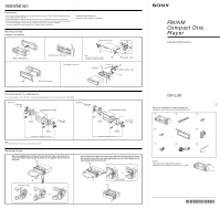
Connections Caution •This unit is designed for negative ground 12 V DC operation only. •Before making connections, disconnect the ground terminal of the car battery to avoid short circuits. •Connect the yellowand red power input leads only after all other leads have been connected. •Be sure to connect the red power input lead to the positive 12 V power terminal which is energized when the ignition key is in the accessory position. •Run all ground wires to a common ground point. •Connect the yellow cord to a free car circuit rated higher than the unit's fuse rating. If you connect this unit in series with other stereo components, the car circuit they are connected to must be rated higher than the sum of the individual component's fuse rating. If there are no car circuits rated as high as the unit's fuse rating, connect the unit directly to the battery. If no car circuits are available for connecting this unit, connect the unit to a car circuit rated higher than the unit's fuse rating in such a way that if the unit blows its fuse, no other circuits will be cut off. •Connecting this unit may cause some car battery wear when your car has no ACC (accessory) position on the ignition key switch. In this case, please consult your nearest Sony dealer. •The use of optical instruments with this product will increase eye hazard. Reset button When the installation and connections are over, be sure to press the reset button with a ball-point pen etc. Reset button Connection example Fuse (10 A) to power antenna control lead or power supply lead of antenna booster amplifier In case of without power antenna, or antenna booster, not necessary to connect this lead. ANTREM Blue Max. supply current 0.1 A Left Front speakers Right White Gray LINE OUT REAR L R from car antenna 8 RCA pin cord (not supplied) Rear speakers Power amplifier (not supplied) Blue/White AMP REM Max. supply current 0.3 A AMP REMOTE IN Red to the +12 V power terminal which is energized in the accessory position of the ignition key Be sure to connect the black ground lead to it first Left Rear speakers Right Green Purple Yellow Black to the +12 V power terminal which is energized at all times Be sure to connect the black ground lead to it first. to a metal point of the car First connect the black ground lead, then connect the yellow and red power input leads. eadsl olrcnt het onNeost • The ANT REM lead (blue) supplies +12 V DC when you turn on the tuner. • A power antenna without relay box cannot be used with this unit. ocnnietMchdoelmoyr When the yellow power input lead is connected, power will always be supplied to the memory circuit even when the ignition key is turned off. oncintecpseakeronNeost • Before connecting the speakers, turn the unit off. • Use speakers with an impedance of 4 to 8 ohms, and with adequate power handling capacities. Otherwise, the speakers may be damaged. • Do not connect the terminals of the speaker system to the car chassis, and do not connect the terminals of the right speaker with those of the left speaker. • Do not attempt to connect the speakers in parallel. • Do not connect any active speakers (with built-in amplifiers) to the speaker terminals of the unit. Doing so may damage the active speakers. Therefore, be sure to connect passive speakers to these terminals. Connection diagram Example 1 Example 2 Front speakers Rear speakers LINE OUT REAR Power amplifier Front speakers Rear speakers Rear speakers
-
 1
1 -
 2
2
 |
 |
