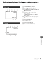
Sony DCRHC54 User Manual - Page 70
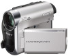
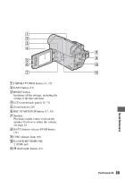
Identifying parts and controls Continued, For DCR-HC51E/HC53E
 |
View all Sony DCRHC54 manuals
Add to My Manuals
Save this manual to your list of manuals |
Page 70 highlights
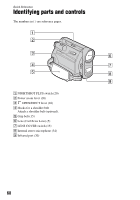
Identifying parts and controls (Continued) A POWER switch (13) B Viewfinder (15) C Eyecup (64) D Viewfinder lens adjustment lever (15) E For DCR-HC51E/HC53E: DV OUT interface (43) For DCR-HC52E/HC54E: DV interface (43, 45) F DC IN jack (10) G A/V Remote Connector (26, 43) H CAMERA, PLAY/EDIT lamp (13) I REC START/STOP button (17, 19) J Tripod receptacle Attach the tripod (optional: the length of the screw must be less than 5.5 mm (7/32 in.)) to the tripod receptacle using a tripod screw. 70
-
 1
1 -
2
-
3
-
4
-
5
-
6
-
7
-
8
-
9
-
10
-
11
-
12
-
13
-
14
-
15
-
16
-
17
-
18
-
19
-
20
-
21
-
22
-
23
-
24
-
25
-
26
-
27
-
28
-
29
-
30
-
31
-
32
-
33
-
34
-
35
-
36
-
37
-
38
-
39
-
40
-
41
-
42
-
43
-
44
-
45
-
46
-
47
-
48
-
49
-
50
-
51
-
52
-
53
-
54
-
55
-
56
-
57
-
58
-
59
-
60
-
61
-
62
-
63
-
64
-
 65
65 -
 66
66 -
 67
67 -
 68
68 -
 69
69 -
 70
70 -
 71
71 -
 72
72 -
 73
73 -
 74
74 -
 75
75 -
76
 |
 |

70
A
POWER switch (13)
B
Viewfinder (15)
C
Eyecup (64)
D
Viewfinder lens adjustment lever (15)
E
For DCR-HC51E/HC53E:
DV OUT interface (43)
For DCR-HC52E/HC54E:
DV interface (43, 45)
F
DC IN jack (10)
G
A/V Remote Connector (26, 43)
H
CAMERA, PLAY/EDIT lamp (13)
I
REC START/STOP button (17, 19)
J
Tripod receptacle
Attach the tripod (optional: the length of
the screw must be less than 5.5 mm
(7/32 in.)) to the tripod receptacle using
a tripod screw.
Identifying parts and controls (Continued)