Sony FCBEX990DP User Manual (FCB-990D_Technical_Manual) - Page 12
Title Display, Synchronization methods, User Memory Area, Privacy Zone Settings, Motion detection
 |
View all Sony FCBEX990DP manuals
Add to My Manuals
Save this manual to your list of manuals |
Page 12 highlights
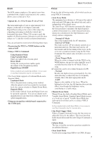
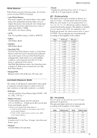
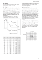
Basic Functions User Memory Area A user area of 16 bytes allows you to write data, such as an ID for each customer, data for each system, and so on, freely. Note Rewriting of memory is not unlimited. Be careful to avoid using the memory area for such as unnecessary tasks as rewriting the contents of the memory for every operation. Privacy Zone Settings For details, see page 13. Motion detection For details, see page 17. Title Display • You can set a title composed of up to 11 lines. One line can contain up to 20 characters. • You can set display on/off, the horizontal position of the first character, blinking state and color for each line. • The camera gives priority to lines of a title when the camera status is displayed on the relevant line. On the lines where a title is not set, the camera status is displayed. Line Number H-position Blink Color 00 to 0A 00 to 17 00: Does not blink 01: Blinks 00 White 01 Yellow 02 Violet 03 Red 04 Cyan 05 Green 06 Blue 00 01 02 03 04 05 06 07 A B C D E F G H 08 09 0a 0b 0c 0d 0e 0f I J K LMN O P 10 11 12 13 14 15 16 17 Q R S T UV W X 18 19 1a 1b 1c 1d 1e 1f Y Z & ? ! 1 2 20 21 22 23 24 25 26 27 3 4 5 6 7 8 9 0 28 29 2a 2b 2c 2d 2e 2f À È Ì ÒÙÁ É Í 30 31 32 33 34 35 36 37 Ó Ú Â Ê ÔÆŒ à 38 39 3a 3b 3c 3d 3e 3f ÕÑ Ç ß Ä Ï Ö Ü 40 41 42 43 44 45 46 47 Å $ F ¥ DM £ ¿ ¡ 48 49 4a 4b 4c 4d 4e 4f ø " : ' . , / - Synchronization methods Internal and external synchronization are available; VISCA Commands allow you to switch between them. • Internal synchronization An internal vibrator inside the camera generates a synchronizing signal as a basic oscillator. NTSC=28.636363MHz PAL=17.7344MHz • External synchronization (V-Lock Synchronization 1)) When a TTL level V-Lock pulse is input, the camera synchronizes to the input signal (V-lock synchronization). The frequency of the input signal synchronizes to within ±1Hz of the external synchronization. Also, 360 degree phase adjustment is possible due to the phase adjustment of the V-lock signal. Because V-lock synchronization is a simple synchronization method, color signals like a VBS "Genlock" signal cannot be synchronized. 1)In V-lock synchronization, the camera makes a V-lock pulse (VL-PULSE) which synchronizes to the commercial power supply and uses it as the external synchronization input signal of the camera, using the fact that the V cycle (59.97 Hz vertical synchronization signal) and the frequency of the commercial power supply (60 Hz). The synchronous signal of the camera will automatically sychronizes to the VL-PULSE in the camera. 12
-
 1
1 -
2
-
3
-
4
-
5
-
6
-
 7
7 -
 8
8 -
 9
9 -
 10
10 -
 11
11 -
 12
12 -
 13
13 -
 14
14 -
 15
15 -
 16
16 -
 17
17 -
18
-
19
-
20
-
21
-
22
-
23
-
24
-
25
-
26
-
27
-
28
-
29
-
30
-
31
-
32
-
33
-
34
-
35
-
36
-
37
-
38
-
39
-
40
-
41
-
42
-
43
-
44
-
45
-
46
-
47
-
48
-
49
-
50
-
51
-
52
 |
 |