Sony HBD-TZ130 Service Manual - Page 2
Ver. 1.2 - model hbd -
 |
View all Sony HBD-TZ130 manuals
Add to My Manuals
Save this manual to your list of manuals |
Page 2 highlights
HBD-TZ130 Ver. 1.2 Tuner Section System PLL quartz-locked digital synthesizer Tuning range North American and Brazilian models: 87.5 MHz - 108.0 MHz (100 kHz step) Other models: 87.5 MHz - 108.0 MHz (50 kHz step) Antenna (aerial) terminals 75 ohms, unbalanced Intermediate frequency 10.7 MHz Video Section Outputs VIDEO: Pin jack HDMI OUT: HDMI 19-pin General Power requirements North American models: 120 V AC, 60 Hz Argentine models: 220 V - 240 V AC, 50/60 Hz Brazilian models: 127 V - 240 V AC, 50/60 Hz Latin American models: 110 V - 240 V AC, 50/60 Hz Other models: 220 V - 240 V AC, 50/60 Hz Power consumption On: 67 W Standby:
-
 1
1 -
 2
2 -
 3
3 -
 4
4 -
 5
5 -
 6
6 -
 7
7 -
 8
8 -
9
-
10
-
11
-
12
-
13
-
14
-
15
-
16
-
17
-
18
-
19
-
20
-
21
-
22
-
23
-
24
-
25
-
26
-
27
-
28
 |
 |
HBD-TZ130
2
Tuner Section
System
PLL quartz-locked
digital synthesizer
Tuning range
North American and Brazilian models:
87.5 MHz - 108.0 MHz
(100 kHz step)
Other models:
87.5 MHz - 108.0 MHz
(50 kHz step)
Antenna (aerial) terminals
75 ohms, unbalanced
Intermediate frequency
10.7 MHz
Video Section
Outputs
VIDEO: Pin jack
HDMI OUT: HDMI
19-pin
General
Power requirements
North American models:
120 V AC, 60 Hz
Argentine models:
220 V - 240 V AC,
50/60 Hz
Brazilian models:
127 V - 240 V AC,
50/60 Hz
Latin American models:
110 V - 240 V AC,
50/60 Hz
Other models:
220 V - 240 V AC,
50/60 Hz
Power consumption
On: 67 W
Standby: <1 W*
*
Valid when the system is in the following status:
– [Control for HDMI] is set to [Off].
Dimensions (approx.)
360 mm × 56 mm ×
342 mm (14
1
/
4
in ×
2
1
/
4
in × 13
1
/
2
in) (w/h/d)
incl. projecting parts
Mass (approx.)
2.6 kg (5 lb. 12 oz.)
Design and speci
fi
cations are subject to
change without notice.
SPECIAL
COMPONENT
NOTICE
The components identi
fi
ed by mark
9
contain con
fi
dential infor-
mation.
Strictly follow the instructions whenever the components are re-
paired and/or replaced.
SAFETY-RELATED
COMPONENT
WARNING!
COMPONENTS
IDENTIFIED
BY
MARK
0
OR
DOTTED
LINE
WITH
MARK
0
ON
THE
SCHEMATIC
DIAGRAMS
AND
IN
THE
PARTS
LIST
ARE
CRITICAL
TO
SAFE
OPERATION.
REPLACE
THESE
COMPONENTS
WITH
SONY
PARTS
WHOSE
PART
NUMBERS
APPEAR
AS
SHOWN
IN
THIS
MANUAL
OR
IN
SUPPLEMENTS
PUBLISHED
BY
SONY.
ATTENTION
AU
COMPOSANT
AYANT
RAPPORT
À
LA
SÉCURITÉ!
LES
COMPOSANTS
IDENTIFIÉS
PAR
UNE
MARQUE
0
SUR
LES
DIAGRAMMES
SCHÉMATIQUES
ET
LA
LISTE
DES
PIÈCES
SONT
CRITIQUES
POUR
LA
SÉCURITÉ
DE
FONC-
TIONNEMENT.
NE
REMPLACER
CES
COMPOSANTS
QUE
PAR
DES
PIÈCES
SONY
DONT
LES
NUMÉROS
SONT
DON-
NÉS
DANS
CE
MANUEL
OU
DANS
LES
SUPPLÉMENTS
PUBLIÉS
PAR
SONY.
NOTICE
POUR
COMPOSANTS
SPÉCIAUX
Les composants identi
fi
és par la marque
9
contiennent des infor-
mations con
fi
dentielles.
Suivre scrupuleusement les instructions chaque fois qu’un compo-
sant est remplacé et / ou réparé.
Ver. 1.2
SAFETY
CHECK-OUT
(US
MODEL)
After correcting the original service problem, perform the follow-
ing safety check before releasing the set to the customer:
Check the antenna terminals, metal trim, “metallized” knobs,
screws, and all other exposed metal parts for AC leakage.
Check leakage as described below.
LEAKAGE
TEST
The AC leakage from any exposed metal part to earth ground and
from all exposed metal parts to any exposed metal part having a
return to chassis, must not exceed 0.5 mA (500 microamperes.).
Leakage current can be measured by any one of three methods.
1.
A commercial leakage tester, such as the Simpson 229 or RCA
WT-540A. Follow the manufacturers’ instructions to use these
instruments.
2.
A battery-operated AC milliammeter. The Data Precision 245
digital multimeter is suitable for this job.
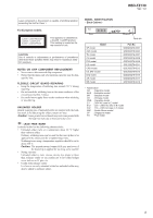
3. Measuring the voltage drop across a resistor by means of a
VOM or battery-operated AC voltmeter. The “limit” indication
is 0.75 V, so analog meters must have an accurate low-voltage
scale. The Simpson 250 and Sanwa SH-63Trd are examples
of a passive VOM that is suitable. Nearly all battery operated
digital multimeters that have a 2 V AC range are suitable. (See
Fig. A)
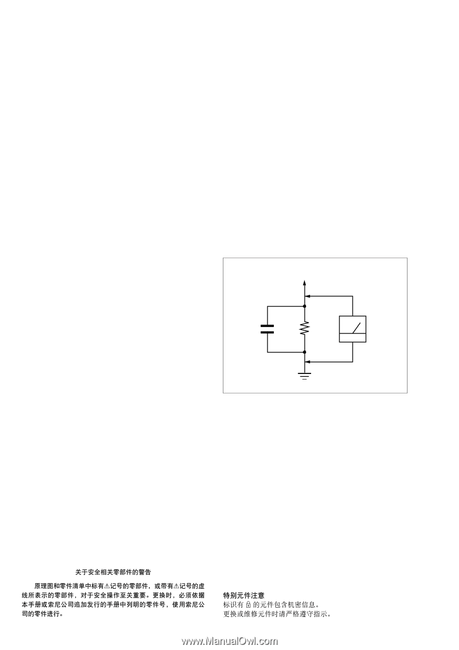
±²³ N´
0.15
μ
F
AC
voltmeter
(0.75 V)
To Exposed Metal
Parts on Set
Earth Ground
Fig. A.
Using an AC voltmeter to check AC leakage.